High Precision Code Plates and Geophones

a high-precision, geophone technology, applied in the direction of instruments, measurement devices, seismic signal receivers, etc., can solve the problems of limited resolution, difficult practical use, limited the precision of measurements made with conventional code plate systems to about 100 nm, etc., to achieve high accuracy, enhance precision, and accurately resolve high spatial frequencies

Inactive Publication Date: 2008-12-04
BOARD OF SUPERVISORS OF LOUISIANA STATE UNIV & AGRI & MECHANICAL COLLEGE
View PDF4 Cites 41 Cited by
  • Summary
  • Abstract
  • Description
  • Claims
  • Application Information

AI Technical Summary

Benefits of technology

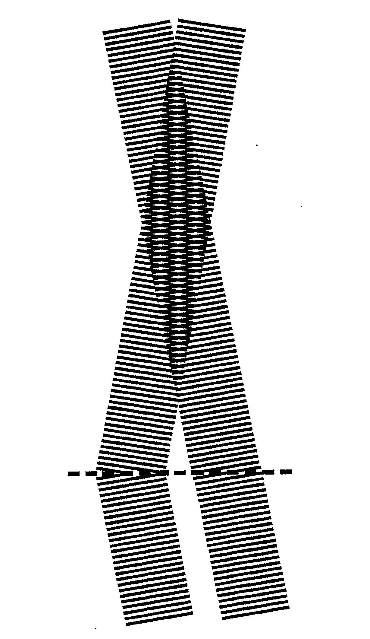
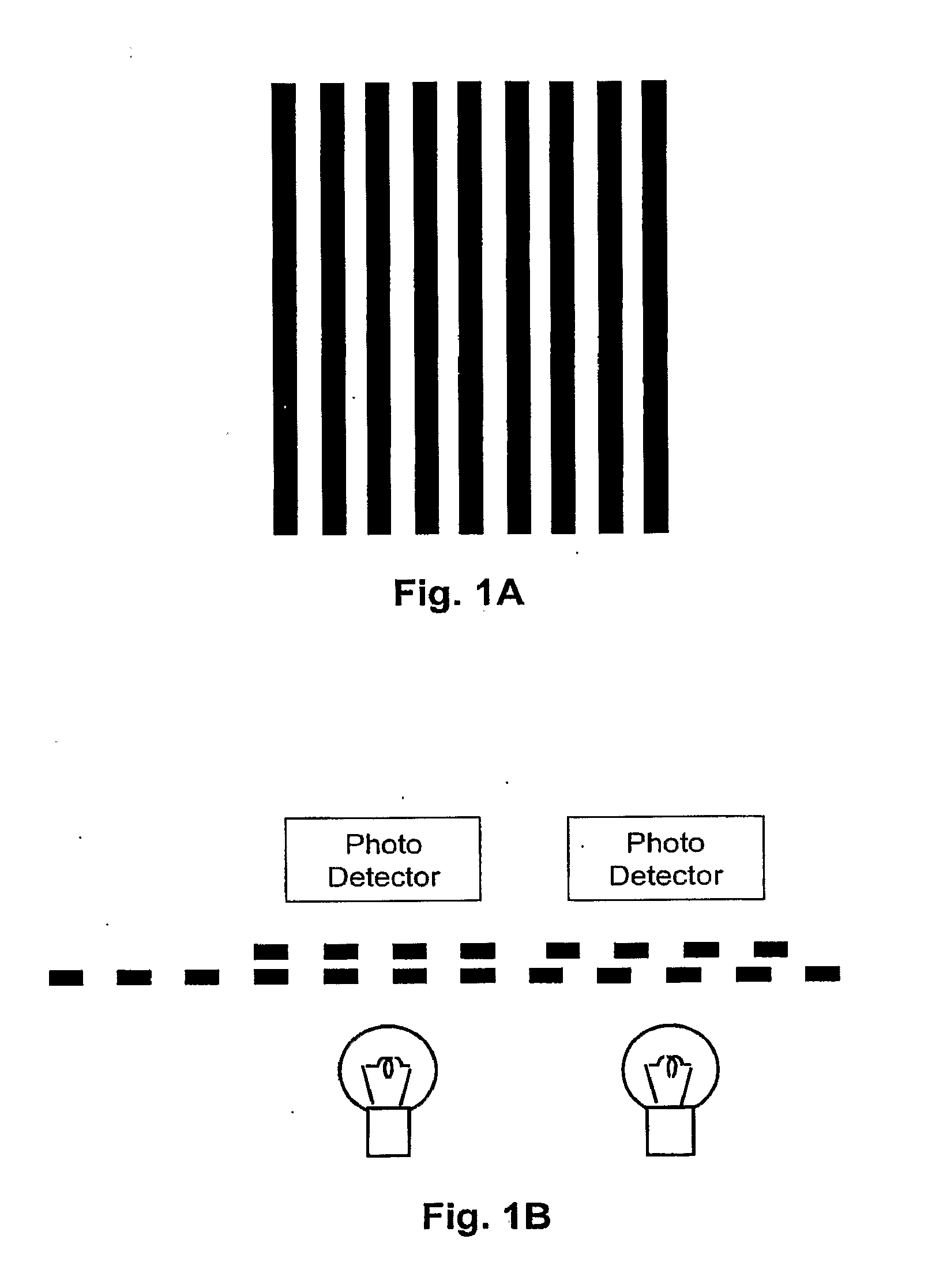
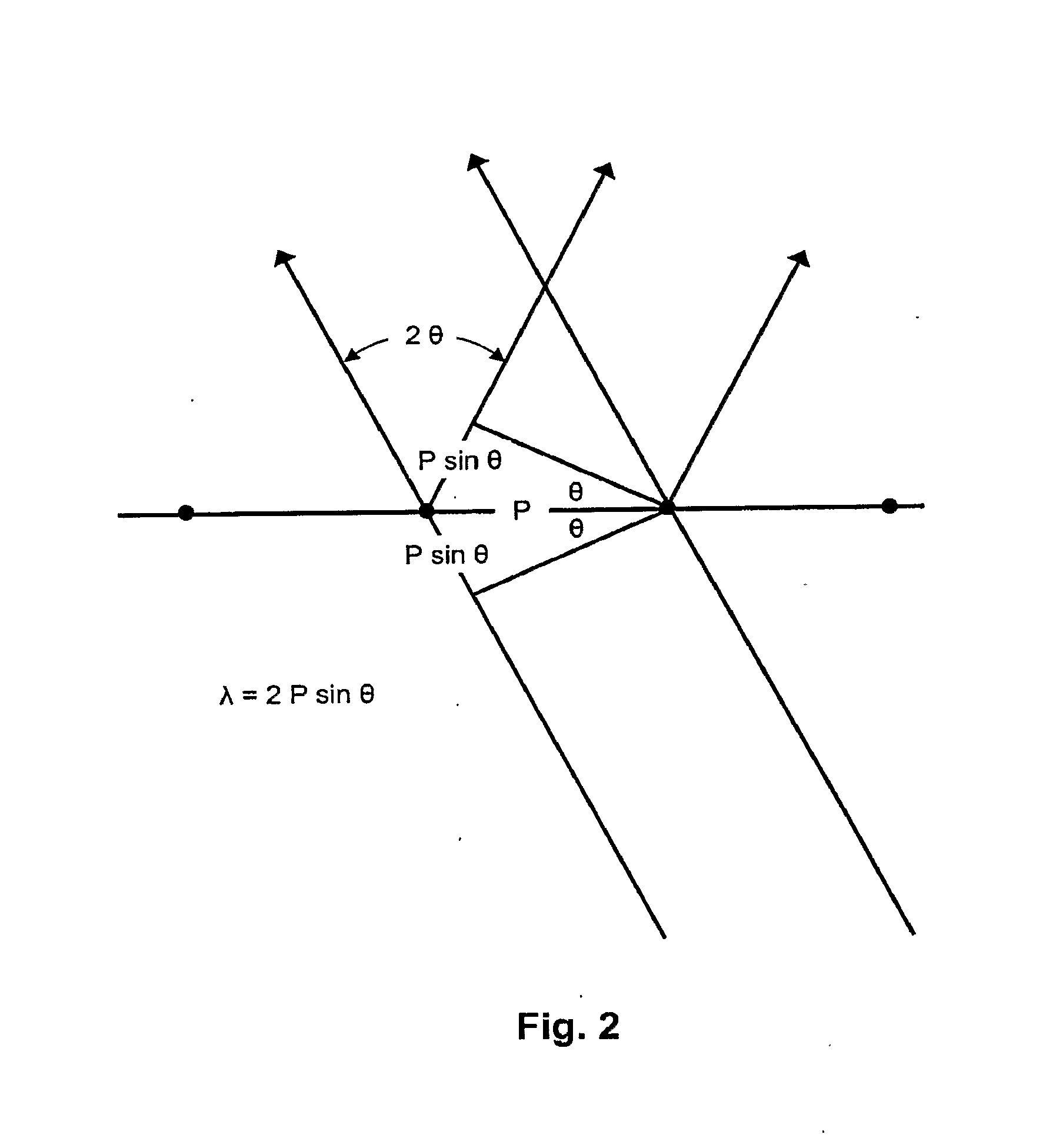
[0018]We have discovered an apparatus and method for imaging a diffraction grating with a very large depth of focus, using a highly accurate code plate position measurement system. Optical techniques are used to enhance the precision with which gratings are used as code plates, to accurately resolve high spatial frequencies with high contrast, with a large depth of focus, and very high precision. An interference fringe “representation” of the grating is formed a distance from the grating. This representation is imaged, for example with an optical microscope, onto a second grating that is positioned at a distance from the first grating. The first diffraction grating is illuminated on one side by one or more mutually coherent beams, preferably laser beams, so that a zero order beam and a first order beam emerge from the other side of the diffraction grating at equal and opposite angles. (Alternatively, a reflection grating might be used instead.) These beams interfere, forming a fringe pattern perpendicular to the grating, with the same period as the grating, and having a fixed phase with respect to the grating. By employing more than one incident beam, the fringes may be given very high contrast over a very large depth of focus centered a substantial distance from the grating. The fringes, or preferably an enlarged image of the fringes, is proje...

Problems solved by technology

Their resolution is limited by the relatively coarse rulings on the code plate and the detection gratings.
The accuracy of determining the phase of a typical sinusoidal output measurement is typically on the order of one part per thousand, due to signal/noise and other limitations.
However, such a fine pitch requires a correspondingly fine depth of focus in conventional systems, making them very difficult to use as a practical matter.
Such factors have typically limited the precision of measurements made with conventional code plate systems to about 100 nm.
This method requires either a small gap between the code plate and the gratings, which is difficult to maintain as a practical matter, or it inherently degrades the resolution of the shadow cast on the gratings if a larger gap is used as a compromise measure.
The sharpness of ...

Method used


Image

  • High Precision Code Plates and Geophones
  • High Precision Code Plates and Geophones
  • High Precision Code Plates and Geophones

Examples


examples and experimental

RESULTS

[0031]Gratings having periods of 1.1 and 0.56 μm have been imaged using the novel technique. The gratings were imaged onto an NTSC format video camera with an Olympus microscope, and frames were “grabbed” for later analysis. The microscope had a 50× objective with an NA of 0.8, a 100× air objective with an NA of 0.9, and a 100× oil immersion objective with an NA of 1.30. Images were taken in white light, and in transmitted HeNe laser light at 0.6328 μm, using Talbot illumination, oblique illumination, and the novel two-beam oblique illumination. We successfully imaged the 0.56 μm period grating at the lowest NA used, 0.8, with both oblique and two-beam oblique illumination, even though the illuminating wavelength was longer than the period of the grating. See FIGS. 5a and 5b of priority application 60 / 753,140. Using Talbot imaging, multiple Talbot images were observed, contaminated by strong coherent artifacts. Strong coherent artifacts were also observed with single beam obl...


PUM


Abstract

An apparatus and method are disclosed for imaging a diffraction grating with a very high depth of focus, using a highly accurate code plate position measurement system. Positions may be measured to an accuracy of 1 nm or even smaller. The system may be used in fields such as manufacturing integrated circuits, and low- and very-low-frequency geophones, and other low- and very-low-frequency acoustic detectors.

Description

[0001](In countries other than the United States:) The benefit of the 22 Dec. 2005 filing date of U.S. provisional patent application 60 / 753,140, and of the 18 Aug. 2006 filing date of U.S. provisional patent application 60 / 838,650 is claimed under applicable treaties and conventions. (In the United States:) The benefit of the 22 Dec. 2005 filing date of U.S. provisional patent application 60 / 753,140, and of the 18 Aug. 2006 filing date of U.S. provisional patent application 60 / 838,650 is claimed under 35 U.S.C. § 119(e).TECHNICAL FIELD[0002]This invention pertains to an apparatus and method for imaging a diffraction grating with a very high depth of focus, in a highly accurate code plate position measurement system. The invention has many uses, including for example uses in high precision geophones, hydrophones, other low-frequency or very-low-frequency acoustic measuring devices, and in integrated circuit fabrication.[0003]Conventional code plates have been used to measure the pos...

Claims


Application Information

Patent Timeline
IPC IPC(8): G01B11/14
CPCG01V1/16G02B27/42G02B27/4255G02B27/60
Inventor FELDMAN, MARTINJIANG, LI
Owner BOARD OF SUPERVISORS OF LOUISIANA STATE UNIV & AGRI & MECHANICAL COLLEGE
Why Eureka
Try Eureka