Low resistance tunneling magnetoresistive sensor with composite inner pinned layer

a magnetoresistive sensor and composite inner layer technology, applied in the field of composite inner pinned layer, can solve the problems of too high read head application rate, difficult control of ra mean and uniformity, etc., and achieve the effects of reducing noise, reducing ra value, and high mr ratio

Active Publication Date: 2008-12-04
HEADWAY TECH INC
View PDF12 Cites 68 Cited by
  • Summary
  • Abstract
  • Description
  • Claims
  • Application Information

AI Technical Summary

Benefits of technology

[0011]One objective of the present invention is to provide a TMR sensor with a composite inner pinned layer to reduce the RA value while maintaining a high MR ratio and reducing noise compared with prior art MTJs having a conventional pinned layer.
[0013]A further objective of the present invention is to provide a method of forming a TMR sensor that satisfies the first and second objectives and is cost effective.
[0015]In another embodiment, an additional layer may be added between the CoFeB layer and the Ru coupling layer. For example, a CoFe layer may be inserted between the coupling layer and CoFeB layer to enhance crystallization and pinning strength with the outer pinned layer.

Problems solved by technology

However, RA values in the MTJs mentioned above are in the range of 240 to 10000 ohm-um2 which is too high for read head applications.
Although a high MR ratio and low RA have been demonstrated in MTJs having a MgO barrier layer, there are still many issues to be resolved before such configurations can be implemented in a TMR sensor of a read head.
For example, the annealing temperature needs to be lower than 300° C. for read head processing, and rf-sputtered MgO barriers make control of RA mean and uniformity more difficult than with conventional DC-sputtered and subsequently naturally oxidized AlOx barriers.

Method used


Image

  • Low resistance tunneling magnetoresistive sensor with composite inner pinned layer
  • Low resistance tunneling magnetoresistive sensor with composite inner pinned layer
  • Low resistance tunneling magnetoresistive sensor with composite inner pinned layer

Examples


Embodiment Construction

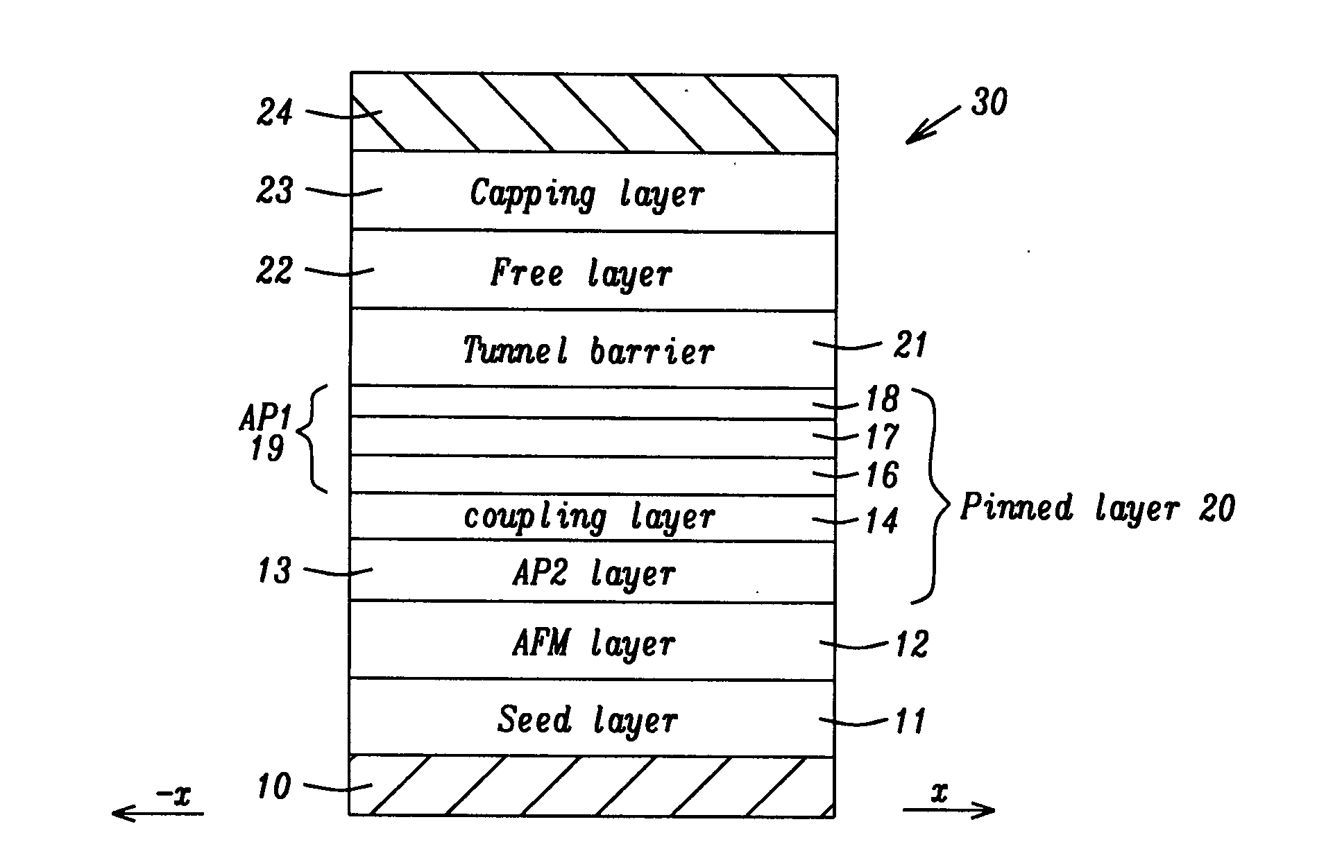
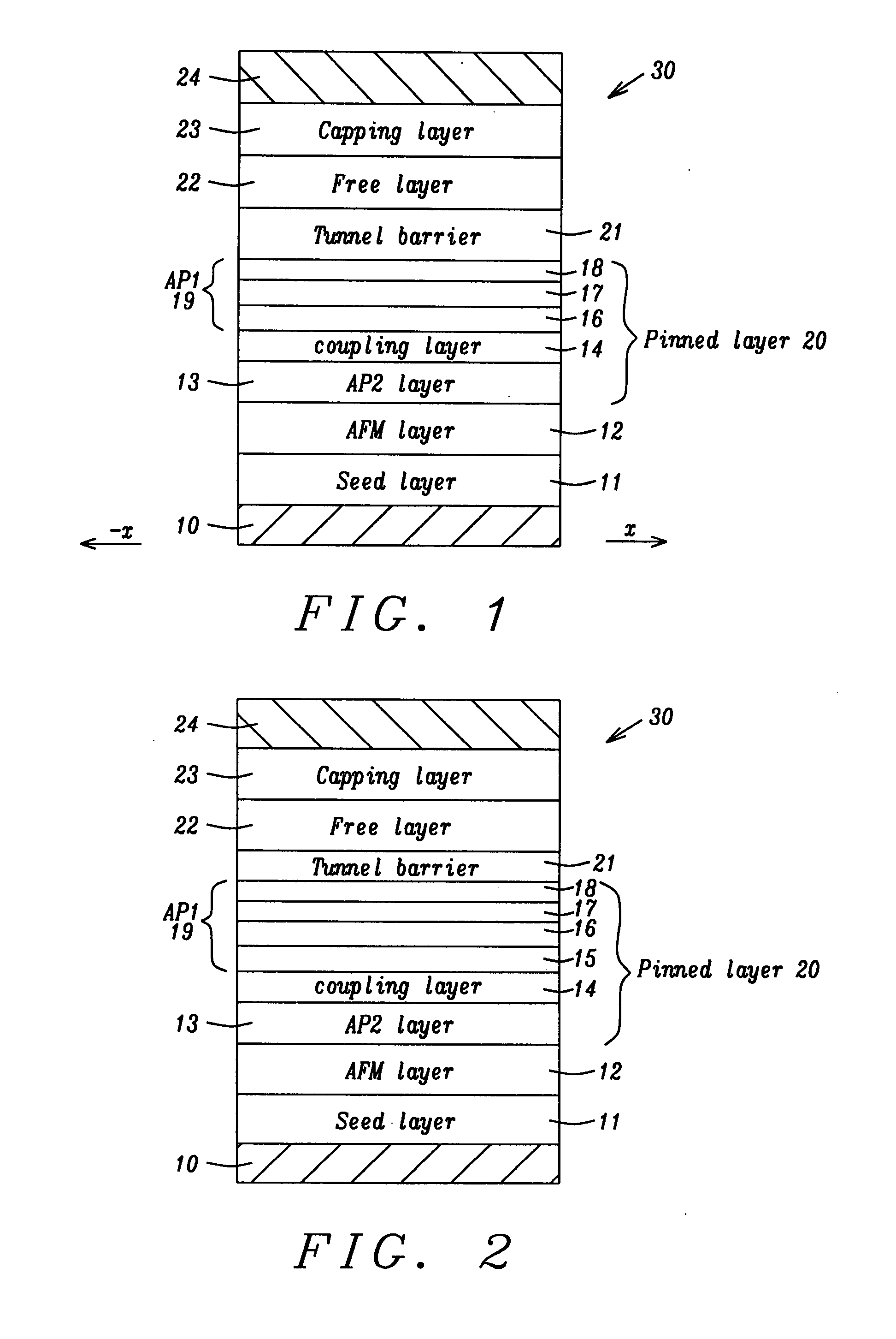
[0023]The present invention is a high performance TMR sensor having a composite inner pinned (AP1) layer comprised of a CoFeB / Fe / Co stack and a method for making the same. While the exemplary embodiment depicts a TMR sensor in a read head, the present invention may be employed in other devices based on a tunneling MR element such as MRAM structures. The TMR sensor may have a bottom spin valve, top spin valve, or multilayer spin value configuration as appreciated by those skilled in the art. The drawings are provided by way of example and are not intended to limit the scope of the invention. For example, the various elements are not necessarily drawn to scale and their relative sizes may differ compared with those in an actual device.

[0024]Referring to FIG. 1, a portion of a partially formed TMR read head 30 of the present invention is shown from the plane of an air bearing surface (ABS). There is a substrate 10 that in one embodiment is a bottom lead otherwise known as a bottom shie...


PUM

PropertyMeasurementUnit
thicknessaaaaaaaaaa
thicknessaaaaaaaaaa
thicknessaaaaaaaaaa

Abstract

A high performance TMR sensor is fabricated by employing a composite inner pinned (AP1) layer in an AP2 / Ru / AP1 pinned layer configuration. In one embodiment, there is a 10 to 80 Angstrom thick lower CoFeB or CoFeB alloy layer on the Ru coupling layer, a and 5 to 50 Angstrom thick Fe or Fe alloy layer on the CoFeB or CoFeB alloy, and a 5 to 30 Angstrom thick Co or Co rich alloy layer formed on the Fe or Fe alloy. A MR ratio of about 48% with a RA of <2 ohm-um2 is achieved when a CoFe AP2 layer, MgO (NOX) tunnel barrier, and CoFe / NiFe free layer are used in the TMR stack. Improved RA uniformity and less head noise are observed. Optionally, a CoFe layer may be inserted between the coupling layer and CoFeB or CoFeB alloy layer to improve pinning strength and enhance crystallization.

Description

RELATED PATENT APPLICATIONS[0001]This application is related to the following: Docket # HT05-023, Ser. No. 11 / 181176, filing date Jul. 14, 2005; and Docket #HT05-045, Ser. No. 11 / 280523, filing date Nov. 16, 2005; both assigned to a common assignee, both of which are herein incorporated by reference in their entirety.FIELD OF THE INVENTION[0002]The invention relates to a high performance tunneling magnetoresistive (TMR) sensor in a read head and a method for making the same, and in particular, to a composite inner pinned layer that reduces the RA (resistance×area) value while maintaining a high MR ratio and reducing head noise.BACKGROUND OF THE INVENTION[0003]A TMR sensor otherwise known as a magnetic tunneling junction (MTJ) is a key component (memory element) in magnetic devices such as Magnetic Random Access Memory (MRAM) and a magnetic read head. A TMR sensor typically has a stack of layers with a configuration in which two ferromagnetic layers are separated by a thin non-magnet...

Claims


Application Information

Patent Timeline
Patent Type & Authority Applications(United States)
IPC IPC(8): H01L21/00
CPCB82Y10/00B82Y25/00B82Y40/00G01R33/098G11B5/3906H01F10/3295H01F10/3254H01F10/3272H01F41/303H01L43/10H01L43/12G11B5/3909H10N50/01H10N50/85
Inventor ZHAO, TONGWANG, HUI-CHUANZHANG, KUNLIANGCHEN, YU-HSIALI, MIN
Owner HEADWAY TECH INC
Why Eureka
Try Eureka