
Dielectric barrier discharge lamp system and driving method thereof having relatively better performance in startup and re-startup of dimming

a technology of dielectric barrier and discharge lamp, which is applied in the direction of dc-ac conversion without reversal, process and machine control, instruments, etc., can solve the problems of not being able to effectively handle problems, affecting the operation of the dc-ac converter, and the wall voltage on the isolation layer is not high enough, so as to improve the startup speed and reduce the startup time. , the effect of improving the startup speed

Inactive Publication Date: 2008-12-11
DELTA ELECTRONICS INC
View PDF2 Cites 3 Cited by
  • Summary
  • Abstract
  • Description
  • Claims
  • Application Information

AI Technical Summary

Benefits of technology

[0010]It is therefore an object of the present invention to provide a DBDL system and the driving method thereof having a relatively better performance in startup and re-startup of dimming, which increase the startup speed via decreasing the startup time. Namely, let the DBDL reach the totally lit up status in a relatively short time. In the present invention, a method of increasing the starting voltage is employed to accomplish the quick startup. The concrete method of increasing the startup speed is to increase the driving voltage applied to the DBDL such that the DBDL is quickly breaking through and enters the totally lit up status. And then, restore the external driving voltage of the DBDL to a normal status. Being verified, this method is quite effective to the quick startup of the DBDL, the effects are more obvious especially during the dimming process, and could dramatically improve the blinking light problem under the relatively lower dimming value of the DBDL. The present invention elaborates a method of employing the burst mode dimming to apply a pulse higher than the normal operating voltage during the startup so as to decrease the blinking light and circuits to accomplish the increasing of the driving pulse voltage during the DBDL startup stage.

Problems solved by technology

This kind of stable square wave is ideal for the stable operation of the FFL, but it can not effectively handle the problems such as the startup and the repeated re-lighting in the burst mode dimming.
It is because the ionization level in the plasma is relatively lower then, and the wall voltage existed on the isolation layer is not high enough relative to that in stable operation.
This causes the problem of relatively harder startup and the light blinking problem in the dimming operations.
The light blinking problem becomes serious especially when the dimming value is relatively lower, which makes the dimming value of the FFL has to be higher than around 20%.
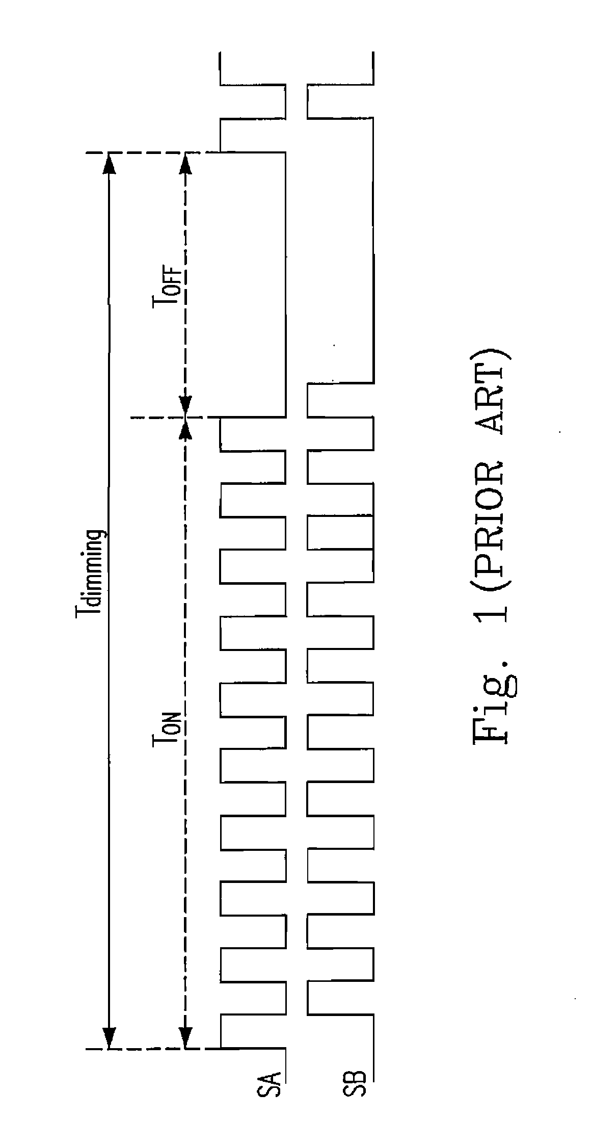
The longer off time makes the combination of the positive ions and the negative ions of the plasma more complete, which makes the re-lighting problem of the FFL become even more difficult.
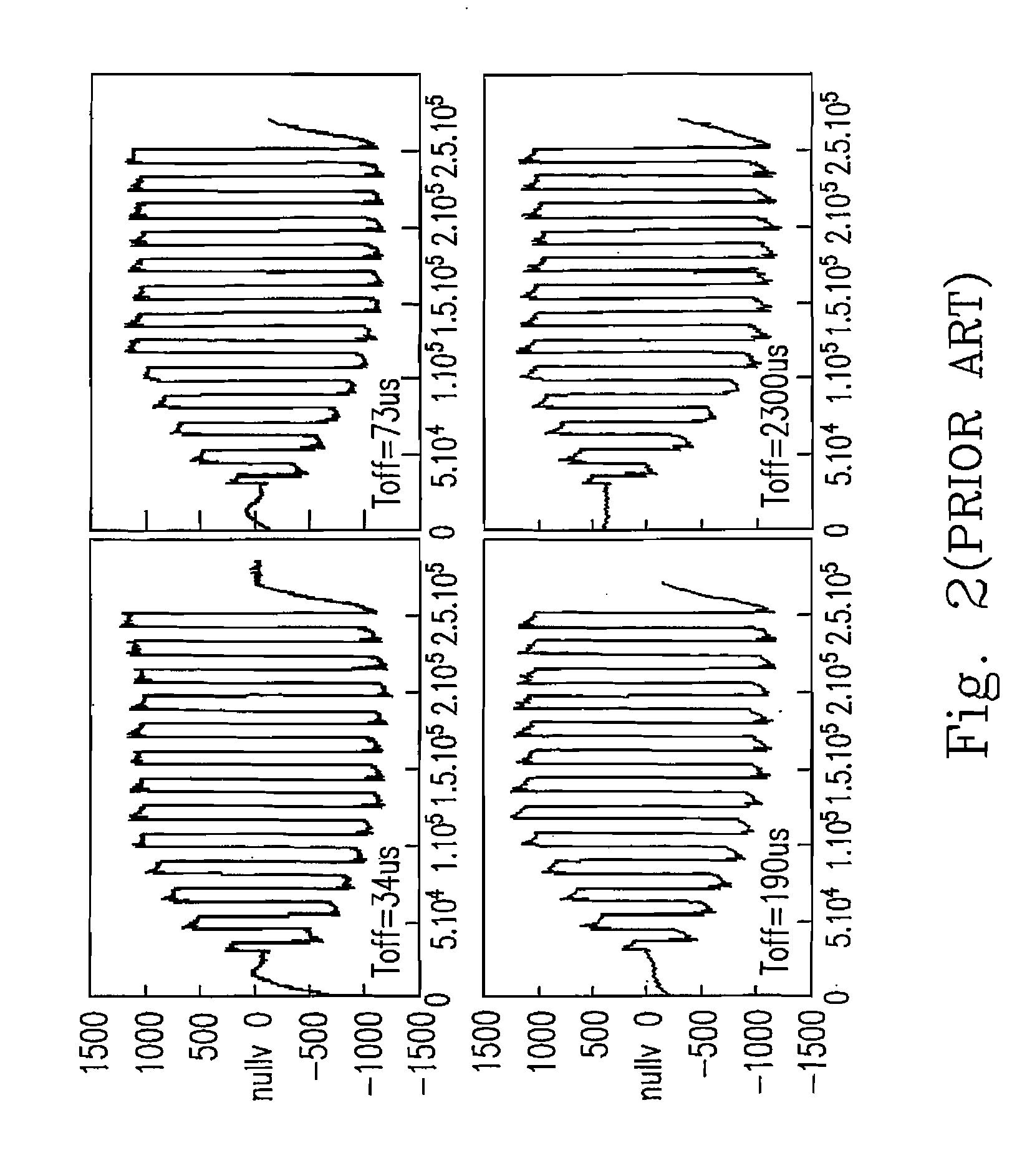
When the FFL is not totally lit up under such a driving situation, the light blinking phenomenon of the FFL does occur, and the light blinking problem will get worse when the dimming value decrease.
As shown by the results of this experiment, the shortened off time can not speed up the re-startup in the dimming operations.
Therefore, decreasing the turn-off time of the dimming operation can not solve the re-lighting problem during the dimming.
Namely, the re-lighting problem always occur no matter what dimming value is, human eyes can not identify it only at the time dimming value is relatively higher.
Since the dimming frequency can not be too low in real operation, this kind of dimming has a relatively larger limitation, a relatively smaller dimming range.
Besides, the energy stored on the isolation layer of the FFL can not be properly released, and will generate the voltage oscillation waves having a frequency lower than the PWM driving frequency, and the energy stored on the FFL is transformed into heat via oscillations and being dissipated when the turn-off time of the burst mode arrives during the burst mode dimming as shown in FIG. 3.
When the next driving period comes, and the voltage oscillation is not diminished yet, which will cause an even larger stress to the transformer, and result in a magnetic bias phenomenon.

Method used


Image

  • Dielectric barrier discharge lamp system and driving method thereof having relatively better performance in startup and re-startup of dimming
  • Dielectric barrier discharge lamp system and driving method thereof having relatively better performance in startup and re-startup of dimming
  • Dielectric barrier discharge lamp system and driving method thereof having relatively better performance in startup and re-startup of dimming

Examples


Embodiment Construction

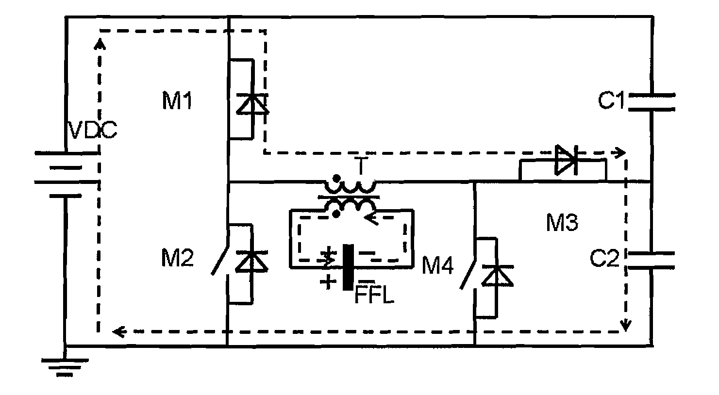
[0049]FIG. 4 shows a schematic circuit diagram of a FFL system having a burst mode dimming circuit according to the first preferred embodiment of the present invention. It is a FFL system having a half-bridge driver circuit. In which, the burst mode dimming circuit includes the switches M3 and M4. The FFL system further includes a DC power source VDC, switches M1 and M2, a transformer T, a FFL and capacitors C1 and C2. FIG. 5 shows the startup operation of the burst mode dimming circuit according to the first preferred embodiment of the present invention. While starting, switches M1 and M4 are turned on, and the voltage across VDC is directed applied to the primary winding of the transformer T. At this moment, the voltage applies to the FFL is twice that of the normal operating voltage. Thus, the FFL could reach the totally lit up status within the time period of the first pulse, and then the switch M4 is turned off, the switch M3 is turned on, and the driver circuit becomes a conve...


PUM


Abstract

The configurations of a dielectric barrier discharge lamp (DBDL) system and the driving method thereof are provided in the present invention. The proposed DBDL system includes a driver circuit receiving a DC input voltage and generating an AC output voltage, including a transformer having a primary winding and a secondary winding, a dielectric barrier discharge lamp coupled to the secondary winding and a burst mode dimming circuit including a first switch. In which, the first switch is turned on when the first switch is starting such that the first switch and the primary winding forms a conducting path so as to apply a driving high voltage to the DBDEL and turn off the first switch after the DBDL is breaking through by the driving high voltage such that a driving normal voltage is applied to the DBDL.

Description

FIELD OF THE INVENTION[0001]The present invention relates to a dielectric barrier discharge lamp (DBDL) system and the driving method thereof. The provided DBDL system could solve the blinking light problem during the burst mode dimming process the DBDL (e.g., a flat fluorescent lamp: FFL).BACKGROUND OF THE INVENTION[0002]FFL is a new type of light source. It possesses the advantages of containing no mercury and relatively having low-profile, long life-span, better uniform brightness and broader operating temperature range etc. It is mainly applied to the backlight systems, the flat lighting and outdoors etc. The FFL is one kind of DBDL. During the driving process of the FFL, there are electrical charges accumulated on an isolation layer to form the reverse potential (the wall voltage) against the driving voltage so as to stop the continuation of the discharging due to the existence of the isolation layer. Therefore, the polarities of the driving voltage have to be changed continuou...

Claims


Application Information

Patent Timeline
IPC IPC(8): H05B37/02H05B41/36H01F27/28H01F27/29
CPCH02M7/48H05B41/2806Y02B20/22Y02B20/00
Inventor HUANG, QIUKAIMENG, QINGYUANYING, JIANPINGHUNG, JIN-CHYUANFRAN, YUI SHIN
Owner DELTA ELECTRONICS INC
Learn More