Catadioptric imaging system, exposure device, and device manufacturing method

Inactive Publication Date: 2008-12-11
NIKON CORP
View PDF1 Cites 9 Cited by
  • Summary
  • Abstract
  • Description
  • Claims
  • Application Information

AI Technical Summary

Benefits of technology

[0007]An embodiment of the present invention to provide a catadioptric imaging optical system with a high numerical aperture including an effective imaging region shaped optimally for use in, for example, a batch type exposure apparatus and having an imaging magnification with a small absolute value. A further embodiment of the present invention is to

Problems solved by technology

However, the miniaturization of mask patterns has increased the mask cost.
When using a single mask for each of various types of semiconductors that are manufactured in small quantities, the chip cost w

Method used


Image

  • Catadioptric imaging system, exposure device, and device manufacturing method
  • Catadioptric imaging system, exposure device, and device manufacturing method
  • Catadioptric imaging system, exposure device, and device manufacturing method

Examples


first example

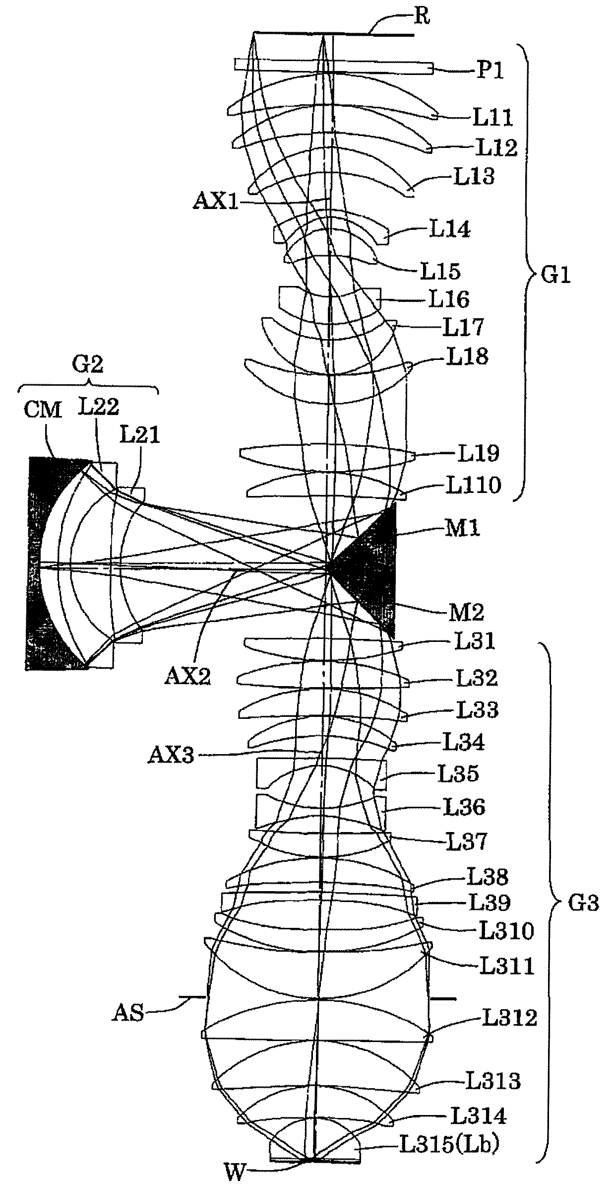
[0050]FIG. 4 is a diagram showing a lens structure of a projection optical system according to a first example of the present embodiment. Referring to FIG. 4, in the projection optical system PL of the first example, the first imaging system G1 includes, sequentially from the reticle side, a plane-parallel plate PI, a positive meniscus lens L11 having a convex surface facing toward the reticle side, a positive meniscus lens L12 having a convex surface facing toward the reticle side, a positive meniscus lens L13 having a convex surface facing toward the reticle side, a negative meniscus lens L14 having an aspherical convex surface facing toward the reticle side, a positive meniscus lens L15 having a convex surface facing toward the reticle side, a negative meniscus lens L16 having a concave surface facing toward the reticle side, a positive meniscus lens L17 having an aspherical concave surface facing toward the reticle side, a positive meniscus lens L18 having a concave surface faci...

second example

[0056]FIG. 6 is a diagram showing a lens structure of a projection optical system according to a second example of the present embodiment. Referring to FIG. 6, in the projection optical system PL of the second example, the first imaging system G1 includes, sequentially from the reticle side, a plane-parallel plate PI, a positive meniscus lens L11 having a convex surface facing toward the reticle side, a positive meniscus lens L12 having a convex surface facing toward the reticle side, a positive meniscus lens L13 having a convex surface facing toward the reticle side, a negative meniscus lens L14 having an aspherical convex surface facing toward the reticle side, a positive meniscus lens L15 having a convex surface facing toward the reticle side, a negative meniscus lens L16 having a convex surface facing toward the reticle side, a negative meniscus lens L17 having a concave surface facing toward the reticle side, a positive meniscus lens L18 having an aspherical concave surface fac...


PUM


Abstract

A catadioptric imaging optical system with a high numerical aperture and including an effective imaging region shaped optimally for use in a batch type exposure apparatus and having an imaging magnification with a small absolute value. The catadioptric imaging optical system includes a dioptric first imaging system, which forms a first intermediate image based on light from the first plane, a second imaging system, which forms a second intermediate image based on light from the first intermediate image, a third dioptric imaging system, which forms a reduced image on the second plane based on light from the second intermediate image, and a deflecting mirror arranged in an optical path extending from the first imaging system to the second imaging system and an optical path extending from the second imaging system to the third imaging system. The first imaging system and the second imaging system provide a composite imaging magnification having an absolute value β12 of less than 0.55, and the third imaging system has an imaging magnification with an absolute value β3 of less than 0.35.

Description

CROSS-REFERENCE TO RELATED APPLICATIONS[0001]This application is a continuation of PCT application number PCT / JP2007 / 051596 filed on Jan. 31, 2007.BACKGROUND OF THE INVENTION[0002]One embodiment of the present invention relates to catadioptric imaging optical system, an exposure apparatus, and a device manufacturing method, and more particularly, to a projection optical system optimal for use in an exposure apparatus employed for manufacturing a micro-device such as a semiconductor device and a liquid crystal display device in a photolithography process.[0003]In a photolithography process for manufacturing a semiconductor device or the like, an exposure apparatus is used to project and expose a pattern image of a mask (or reticle) on a photosensitive substrate (wafer, glass plate, or the like that is coated with photoresist) with a projection optical system. In an exposure apparatus, the projection optical system is required to have a higher resolving power (resolution) since integr...

Claims


Application Information

Patent Timeline
IPC IPC(8): G03B27/54G02B17/00
CPCG02B17/0892G03F7/70225G03F7/70275G03F7/70308G03F7/7055
Inventor OMURA, YASUHIRO
Owner NIKON CORP
Why Eureka
Try Eureka