[0029]FIG. 6B is a top view of a boost IC
package assembly 601 containing the boost converter 501. The structure of the IC
package assembly 601 is similar to the IC package
assembly 600, except the discrete FET 506 is electrically connected to the ground through leads 614 and the controller 504 is electrically connected to the external current sense device 508 at VIN through the bond wires 608. In this case, the insulating
epoxy layer 610 has no stand off requirement since voltage differential is zero, which improves reliability of the boost converter.
[0030]The controller 504 may be manufactured using
Low Voltage CMOS process, which provides better performance, lower
power consumption, and lower die cost due to efficient
layout. The
High Voltage Discrete FET 506 with bottom Source S may be used for the output switch, which provides a much higher
voltage rating without the penalty of die size and
ON resistance. Overall size of the boost converter 500 and 501 may be made compact for
High Voltage and High Power applications.
[0031]FIG. 7 is a
circuit diagram of a boost converter 700 according to another embodiment of the present invention. As shown in FIG. 7, the boost converter 700 may include a
low voltage controller 704 (e.g., a
PWM controller), a bottom source, high voltage discrete FET 706 and a discrete current sense device 708 (e.g., a
resistor or
transistor), all of which are built on a single die pad 702. The controller 704 may be manufactured using a
low voltage CMOS process, which may provide better performance, lower
power consumption, and lower die cost due to efficient
layout. The discrete FET 706 has a bottom source S, gate G and drain D. The
High Voltage Discrete FET 706 with bottom Source may be used for the output switch, which provides a much higher
voltage rating without the penalty of die size and
ON resistance. The discrete current sense device 708 may be used to sense the current at the low-side of the boost converter 700 between the bottom source S and ground. By way of example, the discrete sense device 708 may be a vertical current flow
resistor. As used herein “vertical current flow” means that the resistor is designed so that current flows more or less perpendicular to a plane of a substrate on which the resistor is formed as opposed to flowing along the plane. The bottom source S and sense resistor 708 are electrically connected at a junction J.
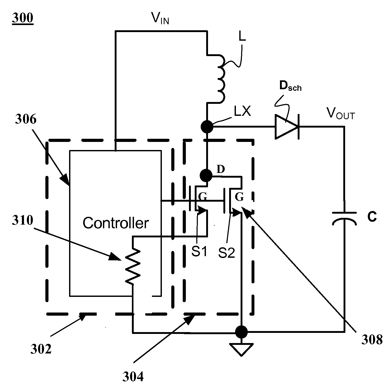
[0034]FIG. 9 is a
circuit diagram of a boost converter 900 of an embodiment of the present invention. As shown in FIG. 9, the boost converter 900 may include first and second die pads 902 and 904. A controller 906 and an internal sense device 910 (e.g., a resistor or
transistor) may be built on the first die pad 902. The controller 906 may be manufactured a Using
Low Voltage CMOS process, which can provide better performance, lower
power consumption, and lower die cost due to efficient
layout. A high voltage
dual source, discrete FET 908 with gates G, sources S1, S2 and bottom drains D1, D2 and a Bottom
Anode Schottky Diode (BA-SD) 912 may be built on the second die pad 904. The High
Voltage Discrete FET 908, which may be used as an output switch, provides a much higher voltage rating without the penalty of die size and
ON resistance. An
inductor L may be connected between an input voltage pin VIN of the controller 906 and a junction J1. An
anode A of the BA-SD 912 may also be connected to the junction J1. The drains D1, D2 may be coupled together at a junction J2. Junctions J1 and J2 may be electrically connected to each other. The internal sense resistor 910 may be used to sense the current at the low-side of the controller 906 between a first bottom source S1 and a third junction J3, which may be connected to ground. The second bottom source S2 may be coupled directly to the third junction J3. A
capacitor C may be coupled between a
cathode Cs of the
Schottky diode 912 and the third junction J3. There may be a
voltage drop VDIODE across the
Schottky diode DSch. The discrete FET 908 may have a drain to source voltage (VDS) rating up to (VOUT+VDIODE) and
gain to source voltage (VGS) rating up to VIN.

