

Conductive polymer foams, method of manufacture, and articles thereof
a technology of conductive polymer foam and polymer foam, which is applied in the direction of conductors, non-metal conductors, magnetic bodies, etc., can solve the problems of increasing the cost of polymer blend, affecting the compressibility and processability of polymer, and users being often forced to make trade-offs
- Summary
- Abstract
- Description
- Claims
- Application Information
AI Technical Summary
Benefits of technology
Problems solved by technology
Method used
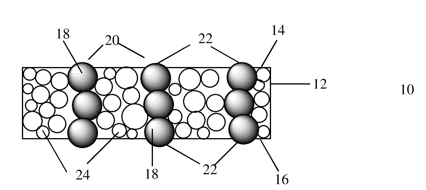
Image


Examples
examples 1-3
[0120]The following test was used to determine conductivity in Examples 1-3, wherein the foams that have a volume resistivity of greater than 103 ohm-cm are comparative. As is known, particular values for volume resistivity and electrostatic shielding will depend on the particular test methods and conditions. For example, it is known that volume resistivity and shielding effectiveness can vary with the pressure placed on the sample during the test. Useful electrical equipment and test fixtures to measure volume resistivity in the sample below are as follows. The fixture is a custom fabricated press with gold plated, 2.5 cm×2.5 cm (1 inch×1 inch) square, and electrical contacts. The fixture is equipped with a digital force gauge that allows the operator to control and make adjustments to the force that is applied to the surface of the sample. The power supply is capable of supplying 0 to 2 amps to the sample surface. The voltage drop and ohms across the sample are measured using a HP...
example 1
[0121]An evaluation of nickel and nickel-coated ceramic microspheres as conductive fillers in a silicone foam was performed. Silicones (Dow Corning Silicone 8137), the filler microspheres, and silicone cure inhibitor (1-octyn-3-ol from Aldrich Chemical Co.) were mixed in a Flaktek speed mixer, cast on a PET film with a controlled thickness, and were placed in an oven exposed to an adjustable magnetic field. In general, the chemically blown and cured foams had a thickness of 70 to 80 mils (1778 to 2032 micrometers).
[0122]The results in Table 1 show that even under a magnetic field as strong as 1200 Gauss, no conductivity was observed in the thick layers of the cured foam.
TABLE 1Run No.1234567Magnetic field, Gauss25025010001000120012001200Casting thickness, mil10202020202020Oven temperature, ° C.23232323232323Oven residence time, min5555101010Top carriernononononononoSi formulation A / B, grams33 / 3.333 / 3.333 / 3.333 / 3.333 / 3.333 / 3.333 / 3.3Inhibitor, drops (about 40 mg)54443—2Filler sphere s...
example 2
[0123]Table 2 shows the results of additional runs using 100% nickel microspheres. Formulations were cast at a thickness of 18 to 40 mil (457 to 1016 micrometers) to prepare foam samples.
TABLE 2Run No.12345678910111213Magnetic field, Gauss1000100010001000100010001000100010001000100010001000Casting thickness, mil20204040402718181818181827Oven temp, ° C.60606060606060606060606060Oven residence time, min101055555555555With top carriernononoyesyesyesyesyesyesyesyesyesyesSi formulation, A / B,33 / 3.333 / 3.333 / 3.333 / 3.333 / 3.333 / 3.333 / 3.333 / 3.350 / 550 / 533 / 3.333 / 3.333 / 3.3gramsInhibitor, drops4444444466444(about 40 mg)Filler sphere size,45-7545-7545-7545-7545-7545-7545-7545-7545-7545-7532-4532-4532-45micrometerFiller loading, grams18243030303033505550506060Nickel column formationyesyesyesyesyesyesyesyesyesyesyesyesyesThickness, mil2123551031259849464647474172Density, PCF38.437.330.23126.12224.726.928.330.830.838.139.9Conductivity*nononononononononononononoFoam qualitypoorpoorpoorgoodgoodgoodgoodg...
PUM
| Property | Measurement | Unit |
|---|---|---|
| pressure | aaaaa | aaaaa |
| density | aaaaa | aaaaa |
| diameter | aaaaa | aaaaa |
Abstract
Description
Claims
Application Information