Neutron detector

a neutron detector and neutron beam technology, applied in the manufacture of electrode systems, electric discharge tubes/lamps, instruments, etc., can solve the problems of limiting the usefulness of many applications, the size and composition of glass micro bubbles are too small to capture all the energy, and the borosilicate glass is generally unsuitable for containing, so as to reduce voltage and power requirements, reduce the effect of neutron discrimination

Inactive Publication Date: 2008-12-25
MATERIALS INNOVATION INC +1
View PDF55 Cites 5 Cited by
  • Summary
  • Abstract
  • Description
  • Claims
  • Application Information

AI Technical Summary

Benefits of technology

[0014]Objects of the present invention include the following: providing a more efficient (sensitive) neutron detector, both on an absolute and a per-volume basis; providing a neutron detector that more effectively discriminates neutrons from other types of ionizing radiation; providing a gas-filled neutron detector with improved signal characteristics; providing a gas-filled neutron detector capable of filling with 3He and further capable of retaining the 3He for an effective period of time; providing a gas-filled neutron detector capable of filling with other neutron-reactive gases such as hydrogen; providing a gas-filled neutron detector with reduced voltage and power requirements; providing a gas-filled neutron detector that is easier and less expensive to manufacture; providing a gas-filled neutron detector of enhanced field-ruggedness; providing a gas-filled neutron detector that can be filled with multiple types of gases; and providing a gas-filled neutron detector that can be formed into many different shapes and sizes. These and other objects and advantages of the invention will become apparent from consideration of the following specification, read in conjunction with the drawings.
[0015]According to one aspect of the invention an apparatus for detecting neutrons comprises: a hollow dielectric body having a bulk resistivity in the range from about 108 to about 1017 Ω-m, the body containing an interior volume of gas capable of at least partial ionization by a neutron; two electrodes in contact respectively with opposite sides of the dielectric body, the electrodes configured to create an electric field across the gas volume, whereby an electrical pulse will be detectable by the electrodes when an ionization event occurs within the interior volume; and, a detection circuit connected to the electrodes, the detection circuit capable of detecting the electrical pulse.
[0016]According to another aspect of the invention, an apparatus for detecting neutrons comprises: a substantially planar array of hollow dielectric shells, the shells filled with a gas capable of at least partial ionization by a neutron; electrodes disposed on opposite sides of the planar array in electrical contact with the hollow dielectric shells whereby an electrical pulse may be collected in response to the passage of the neutron; and, a detection circuit connected to the electrodes, the detection circuit capable of detecting the electrical pulse.
[0017]According to another aspect of the invention, a method of making a neutron detector comprises the steps of:
[0018]a. formulating a glass composition having a bulk resistivity in the range of 108 to 1017 Ω-m and a gas permeability constant for helium at room temperature of less than 7.6×10⁻¹¹ cm3 / sec / cm2 / mm / cm·Hg;
[0019]b. forming the glass into a hollow body having an interior dimension from about 0.1 to about 30 mm and a wall thickness from about 10 μm to about 5 mm;

Problems solved by technology

However, it has several shortcomings that limit its usefulness for many applications: First, the size of the micro bubbles was too small to capture all the energy of the ionizing particle, as stated on p.
A second shortcoming is that, although Kocsis suggests using 3He as the void gas, the size and composition of the glass micro bubbles (1.5 μm wall thickness, borosilicate glass) would be generally unsuitable for containing He, because it would lose roughly 50% of the 3He pressure within three days.
The Henderson device was capable of improved 3He gas retention as compared to the Kocsis device, but would still lose the majority of its 3He gas fill in less than a year, a problem for long-term (practical) use in the field.
Because of this characteristic, the Drukier device does not yield a direct electronic pulse that can be evaluated using pulse height analysis (pulse height discrimination) for neutron-gamma separation.
The Tomassino device does not provide real-time detection (i.e., it measures integrated neutron exposure and does not indicate individual neutrons).

Method used


Image

  • Neutron detector
  • Neutron detector
  • Neutron detector

Examples


example 1

[0057]Theoretical results for one dielectric sensor detector balloon: Tables 1 and 2 below are derived from the results of theoretical calculations of wall effects (edge effects) for neutron reaction products and electrons from gammas. The tables define both the preferred range of parameters estimated to provide optimal performance and the range of parameters estimated to provide useful but non-optimal performance. As these values were derived from theoretical calculations, some lie beyond what is currently practical, given the existing state-of-the-art in materials science. For example, the current upper limit for gas pressure in small sensors is around 103 atmospheres, while for very small sensor sizes (e.g. 10−3 cm) the theoretical maximum pressure is much higher.

TABLE 1Suitable sensor sizes (interior diameter of a sphericaldielectric sensor balloon) as a function of gas density.Gas DensityMinimumPreferredPreferredMaximum(g / cc)Size (cm)Min (cm)Max (cm)Size (cm)1.00E−051.19E+012.3...

example 2

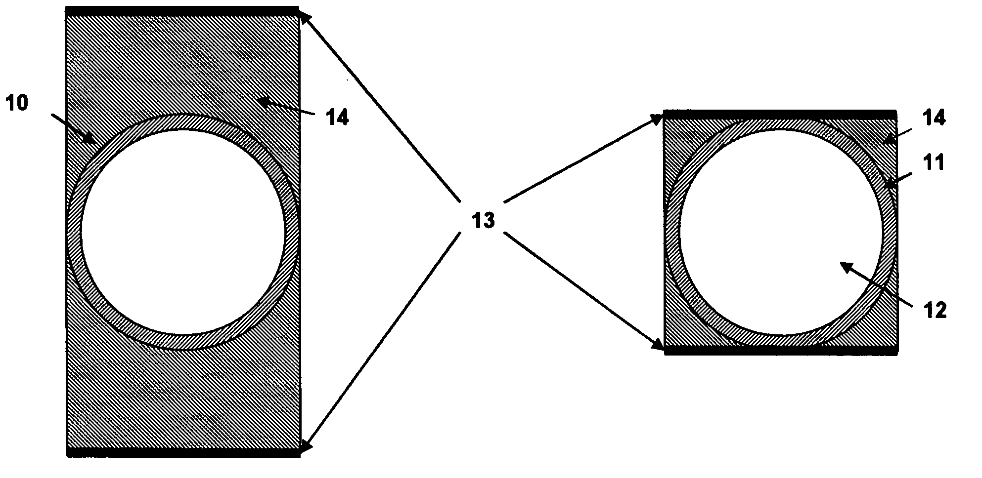
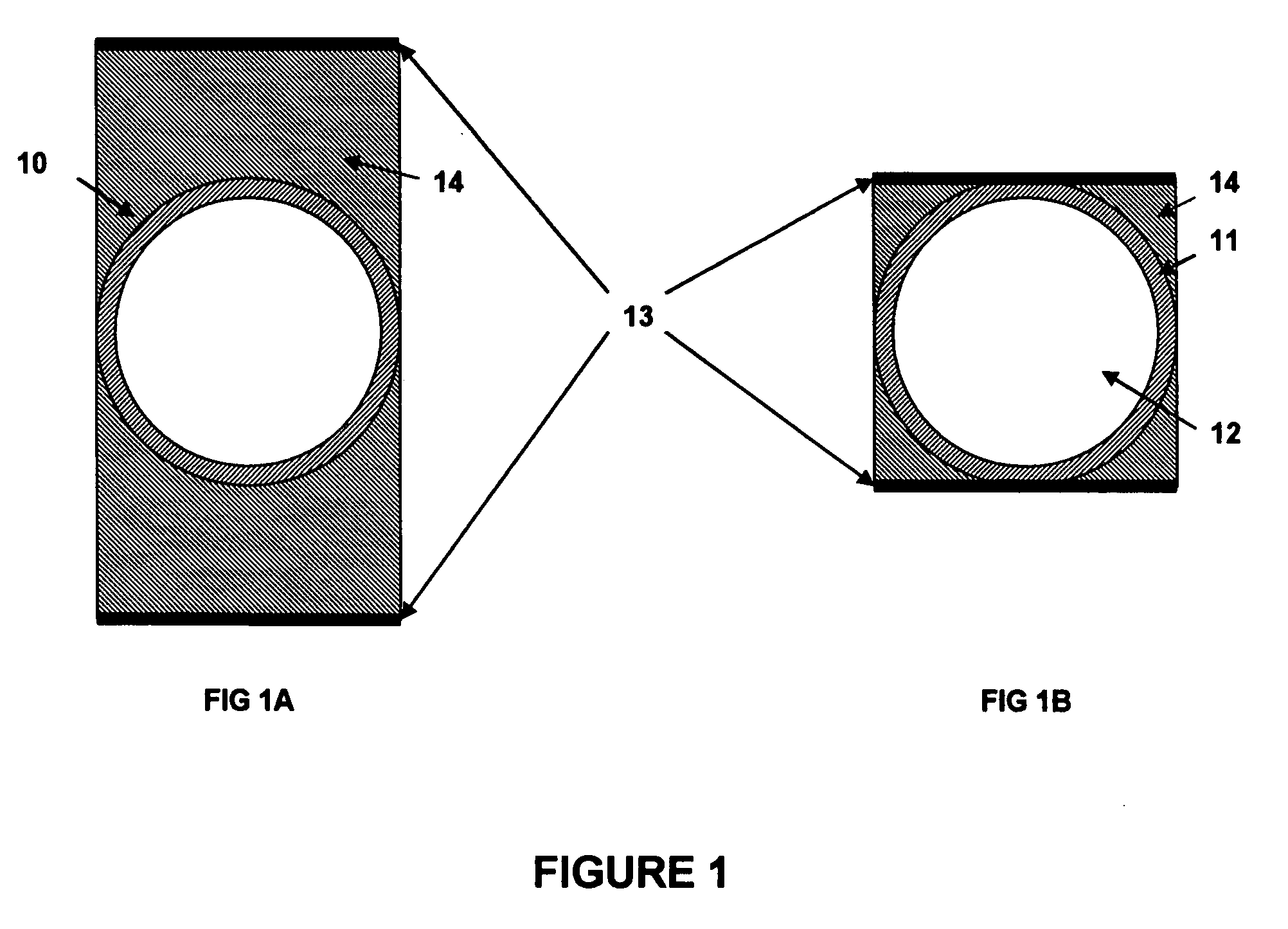
[0059]Applicants constructed a number of dielectric sensors consisting of gas-filled spherical balloons 10 (i.e. having an outer shell 11 and a hollow interior 12 filled with gas). Based on the foregoing calculations, the sensors had an outer diameter of 7 mm with 200 μm thick glass walls 11. The interior 12 of each sensor was filled with a gas mixture consisting of 3 atm 3He and 5 atm Ar. This combination of gas composition, gas pressure, and sensor size was sufficient for most 3He neutron capture events to deposit much or all of the energy released from the neutron capture reaction (in the form of energetic reaction products) in the sensor gas. Simultaneously, the combination of sensor size and gas pressure / density was low enough such that most gamma-induced electrons produced only minimal energy deposition in a sensor.

[0060]The glass consisted of a modified fused silica with a low gas diffusion rate for 3He (estimated 90% retention for at least 30 years) and a resistivity of appr...

example 3

[0076]Assuming a spherical dielectric sensor filled with gas, the fraction of the voltage drop across the gas may be estimated by approximating the electrodes and sensor walls as parallel plates, using the formula:

ΔVgas / ΔVapp=t / [(2tw / k)+t],  [Equation 1]

where ΔVapp is the applied voltage across the electrodes, ΔVgas is the drop in voltage across the sensor gas, k is the dielectric constant of the glass, tw is the wall thickness, and t is the inner circumference of the sensor. These parameters are depicted in FIG. 3. Sensor size and wall thickness may vary, but it can be seen in Equation 1 above that it is the ratio of these values, rather than their absolute values, that matters. Glass dielectric constant can also vary. FIG. 4 shows the fraction of the voltage drop occurring within the sensor gas as a function of glass dielectric constant for different total wall thickness to total sensor size ratios varying from 0.02 to 0.10. The plots cover various preferred ranges of size and wal...


PUM


Abstract

A neutron detector comprises a gas-filled dielectric shell, preferably a glass balloon, having opposite electrodes. An electric field is established whereby ionizing particles may be detected via ionization and current flow in the gas, using a pulse height analyzer or other conventional means. The dielectric shell preferably has low gas permeability and a bulk resistivity in the range of 108 to 1017 Ω-m, and is preferably in the millimeter to centimeter size range. Multiple balloons may be arranged in parallel or may be individually addressable by the detector electronics.

Description

CROSS-REFERENCE TO RELATED APPLICATION[0001]This application contains material disclosed in part in U.S. patent application Ser. No. ______ filed by the present inventors on even date herewith, the entire disclosure of which is incorporated herein by reference.STATEMENT REGARDING FEDERALLY SPONSORED RESEARCH[0002]The United States Government has rights in this invention pursuant to contract No. DE-AC05-00OR22725 between the United States Department of Energy and UT-Battelle, LLC. and Agreement No. HSHQPA-05-9-00047 awarded by the U.S. Department of Homeland Security to Material Innovations, Inc.BACKGROUND OF THE INVENTION[0003]1. Field of the Invention[0004]The invention pertains to apparatus and methods for detecting neutrons and more particularly to neutron detectors having an ionizable gas contained in a dielectric capsule.[0005]2. Description of Related Art[0006]Kocsis has published several papers describing a particle detector using a syntactic foam comprising gas-filled glass ...

Claims


Application Information

Patent Timeline
Patent Type & Authority Applications(United States)
IPC IPC(8): G01T3/00H01J9/00H01J9/20
CPCG01T3/008H01J47/1255
Inventor STEPHAN, ANDREW C.JARDRET, VINCENT D.KISNER, ROGER A.
Owner MATERIALS INNOVATION INC
Why Eureka
Try Eureka