Eureka AIR delivers breakthrough ideas for toughest innovation challenges, trusted by R&D personnel around the world.

Plant And Process For Removing Carbon Dioxide From Gas Streams

a technology for carbon dioxide and gas streams, applied in separation processes, hydrogen sulfides, machines/engines, etc., can solve the problems of inability to meet the needs of customers, so as to reduce the operating pressure

Active Publication Date: 2008-12-25
KC8 CAPTURE TECH LTD
View PDF6 Cites 69 Cited by
  • Summary
  • Abstract
  • Description
  • Claims
  • Application Information

AI Technical Summary

Benefits of technology

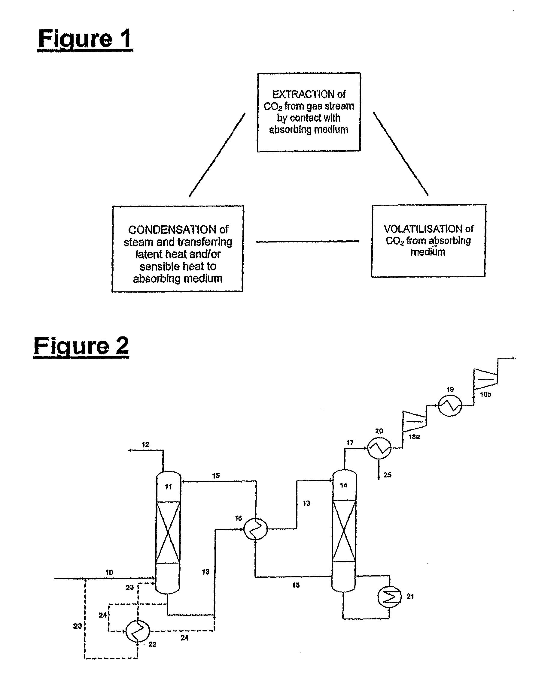
"The present invention provides a process for removing carbon dioxide from gas streams containing steam and carbon dioxide. The process involves using the energy from the gas stream through the use of latent heat of condensation of steam and the sensible heat from the gas stream as a heat source to assist in the volatilization of carbon dioxide. The process can be carried out in a single step or in multiple steps, and recycling of the absorbing medium can be used to further minimize energy requirements. The gas stream can also be treated or stored to prevent leakage to the atmosphere. The process is efficient and effective in separating carbon dioxide from gas streams, and can be carried out in existing processing plants."

Problems solved by technology

However, a rapid move to meet all energy needs through alternative renewable energy sources would be very costly to consumers, damaging to the economy, and at the present time is impractical on a technology basis.
However, the methods currently available are not particularly efficient for removing carbon dioxide from high volume low pressure industrial gas streams having a low concentration of carbon dioxide such as the flue gases generated by conventional coal fired and gas fired power stations.
In particular, the massive volumes of flue gases generated by power stations require large capital investments to handle the flue gas which is seen as a major impediment.
Another difficulty is that a large amount of energy, approximately 30-40% of the total production of a coal powered electrical generation plant would be required to release the carbon dioxide from solvents or solid absorbing mediums after separation from the flue gas.
In addition, technologies such as membrane separation are yet to be adequately scaled up to the level where they can be used to capture carbon dioxide at the scale of coal fired power stations.

Method used


Image

  • Plant And Process For Removing Carbon Dioxide From Gas Streams
  • Plant And Process For Removing Carbon Dioxide From Gas Streams
  • Plant And Process For Removing Carbon Dioxide From Gas Streams

Examples


examples

[0121]The following examples relate to flow sheets involving the use of un-promoted potassium carbonates solvents. However as explained above, it is within the scope of the present invention that the absorbing medium may contain any one or a combination of the active components including, but by no mean limited to, alkali carbonates, amino acids and amines, wherein the active components may be either promoted or un-promoted.

FIGS. 3 and 4

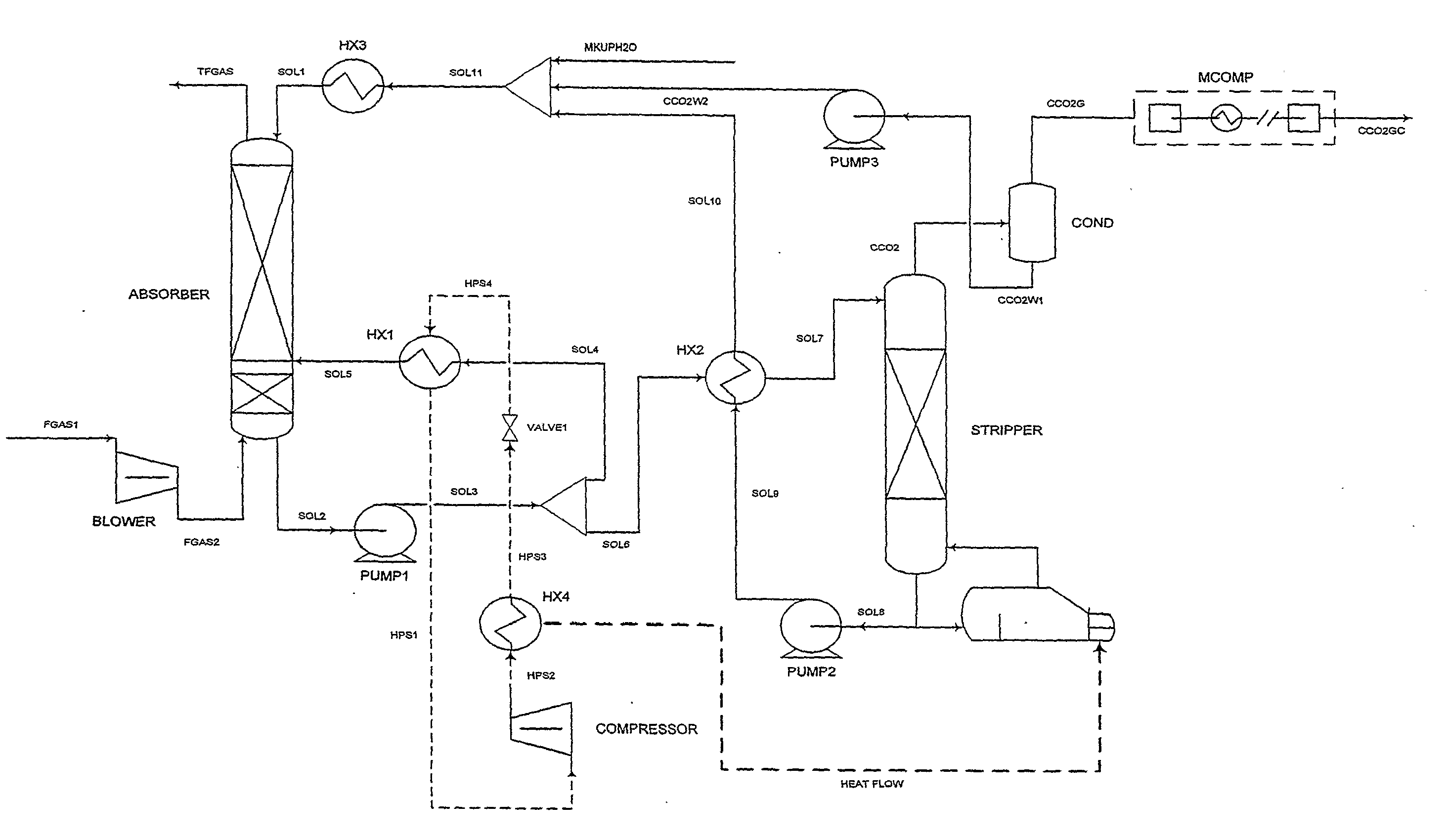
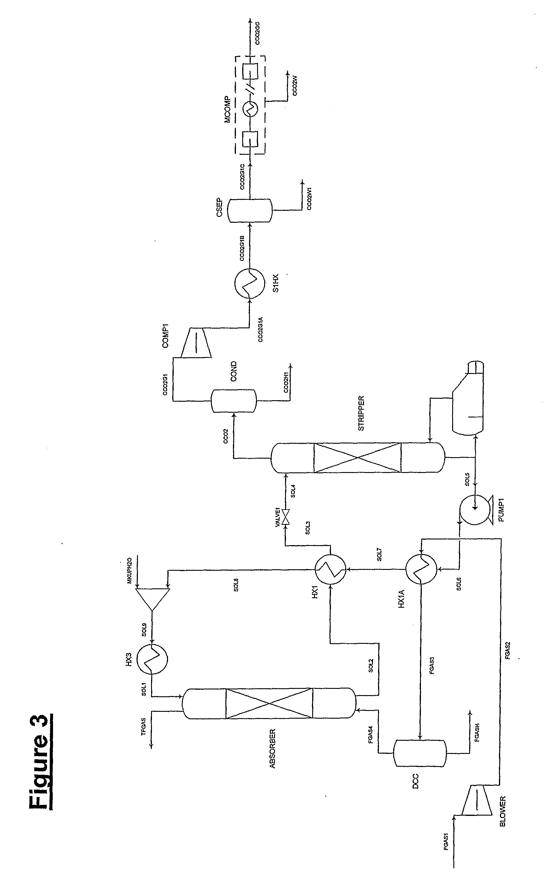
[0122]The flow sheet shown in FIG. 3 is similar to the flow sheet shown in FIG. 2 and includes an absorber, stripper and reboiler and a number of other unit operations specific for handling flue gases from a brown coal fired power station such as a blower. By way of summary, a flue gas stream identified as FGAS4 is feed into the absorber after having being pre-treated in a direct contact cooler (DCC) which is essentially a knock out pot to remove condensed water and a heat exchanger HX1A. Treated flue gas lean in carbon dioxide is discharged from the...


PUM


Abstract

The present invention is based on the realization that the carbon dioxide component of industrial gas streams also containing steam can be processed so to utilize either as latent and / or sensible heat the heat available from the steam component to assist in separating carbon dioxide from the remainder of the gas stream. For example, flue gases produced by power stations burning brown coal, black coal or natural gas inherently contain a useful amount of energy that can be harnessed according to the present invention. According to particular preferred forms of the invention, nitrogen and sulphur constituent such as SOx and NOx, H2S and other nitrogen containing compounds may also be removed from the gas stream through direct contact with the absorbing medium and used to produce by-products such as fertiliser material.

Description

FIELD AND BACKGROUND OF THE PRESENT INVENTION[0001]The present invention relates to a plant and process for removing carbon dioxide from industrial gas streams and effluents with a view to reducing carbon dioxide emissions to the environment.[0002]The concentration of carbon dioxide in the atmosphere has risen from 280 parts per million to 370 parts per million over the last 150 years mainly from increased use of fossil fuels, particularly for electrical power generation and transport. However, a rapid move to meet all energy needs through alternative renewable energy sources would be very costly to consumers, damaging to the economy, and at the present time is impractical on a technology basis.[0003]A reduction in carbon dioxide emissions will be required to stabilize, and in the long term, decrease carbon dioxide concentrations in the atmosphere. A promising technology for significantly decreasing emissions from large scale carbon dioxide emitting plants such as coal fired power s...

Claims


Application Information

Patent Timeline
Patent Type & Authority Applications(United States)
IPC IPC(8): B01D53/04
CPCB01D53/1425B01D53/1475Y02C10/04Y02C10/06Y02C10/08Y02C10/12Y02C20/40
Inventor HOOPER, BARRYSTEVENS, GEOFFKENTISH, SANDRA
Owner KC8 CAPTURE TECH LTD
Why Eureka
Eureka Blog
Learn More