DNA measuring system and method

a technology of dna and measuring system, applied in the field of dna measuring system and method, can solve the problems of small change in interfacial potential per extension reaction of base, difficult detection of extension reaction, and difficulty in reuse of fet sensor, so as to suppress the deterioration in the reproducibility of measurement, high accuracy detection, and the effect of suppressing the deterioration of measurement reproducibility

Inactive Publication Date: 2008-12-25
HITACHI LTD
View PDF0 Cites 55 Cited by
  • Summary
  • Abstract
  • Description
  • Claims
  • Application Information

AI Technical Summary

Benefits of technology

[0014]In order to solve the above problems, according to the present invention, a spherical fine particle having immobilized thereon double-stranded DNA containing a hybridization of a probe DNA and a target DNA is disposed on a metal electrode surface of an extended gate FET sensor that is a metal electrode having a spherical surface on which a sensing unit is in contact with the fine particle, and an extension reaction of the double-stranded DNA is detected through a change in interfacial potential on the surface of the sensor. As employed here, the extended gate FET sensor is an insulated gate field effect transistor sensor in which the metal electrode that is the sensing unit is connected to a gate of an insulated gate field effect transistor by a conductive wiring.
[0015]Generally, the field effect transistor involves leakage current, and thus, a drain current value varies with measuring time independently of the change in the interfacial potential on the insulating layer. For this reason, for detection of the extension reaction through the change in the interfacial potential on the surface of the sensor, it is desirable that a change in the drain current value caused by the change in the interfacial potential after the extension reaction be greater than that caused by the leakage current. As the above condition, the shape of the sensing unit of the FET sensor, as shown in FIG. 1, is determined so that Equations (1) and (2) can be satisfied:
[0016]In order to suppress deterioration in the reproducibility of measurement caused by a change in the position of the fine particle due to Brownian motion thereof, there is provided a mechanism for pressing the fine particle against the surface of the metal electrode, using a flow by a pressure wave, an attraction by a magnetic field, a flow by a change in temperature, or the like. Also, there is provided a mechanism for separating the fine particle from the surface of the metal electrode at the time of a solution change, using the flow by the pressure wave, the attraction by the magnetic field, the flow by the change in temperature, or the like. One and the same mechanism may be used as the mechanism for pressing the fine particle against the surface of the metal electrode and that for separating the fine particle from the surface of the metal electrode.
[0017]The present invention enables sequence determination for DNA with a long base without being limited by the Debye length, which becomes a problem with the existing FET-based DNA sequencer. The use of the metal electrode having the spherical surface in contact with the fine particle as the sensing unit of the FET sensor enables a contact of the spherical surface of the sensing unit with the surface of the fine particle over a wide range, and thus enables the arrangement of a larger number of target DNAs within the Debye length, as compared to the use of a flat metal electrode. Also, the inside of the metal electrode is of equal potential, and thus, the change in the interfacial potential that occurs in any region on the surface of the sensor can effect an equal change in the potential of the gate insulating film regardless of the shape of the metal electrode, thus enabling high-accuracy detection.
[0018]Also, the immobilization of the probe DNA or the target DNA on the spherical fine particle, rather than that directly on the surface of the sensor, enables the reuse of the FET sensor merely by removing the fine particle after sequencing.
[0019]Further, the pressing of the fine particle against the surface of the metal electrode using the flow by the pressure wave, the attraction by the magnetic field, the flow by the change in temperature, or the like enables suppressing the deterioration in the reproducibility of measurement caused by a shift in the position of the fine particle. It is sufficient for the fine particle to be pressed against the surface of the metal electrode simultaneously only when potential measurement by the FET sensor is carried out. Also, the separation of the fine particle from the surface of the metal electrode at the time of the solution change enables an effective solution change.

Problems solved by technology

Thus, the DNA sequencer has the problem of a short length of base detectable in principle, and further has the problem of having difficulty in the reuse of the FET sensor.
Thus, as the extension reaction region becomes farther away from the surface of the sensor with the proceeding of the extension reaction of the probe DNA hybridized with the target DNA, the amount of change in the interfacial potential per extension reaction of base becomes smaller, so that it becomes difficult to detect the extension reaction.
Also, the limit of the readable number of bases is 20 in practice, allowing for the length of a portion hybridized with the probe DNA or the length of a linker bonded to the probe DNA for immobilization on the surface of the sensor, and 50 bases or more are required to uniquely map sequence information onto the reference genome sequence after sequence determination (see Nucleic Acids Research 2005, Vol. 33. e171), which in turn makes it difficult to use this DNA sequencer for typical sequencing.
However, this requires a complicated process using a special chemical solvent or the like, thus makes it difficult to reuse the FET sensor, and hence leads to an increase in the running cost.

Method used


Image

  • DNA measuring system and method
  • DNA measuring system and method
  • DNA measuring system and method

Examples


first embodiment

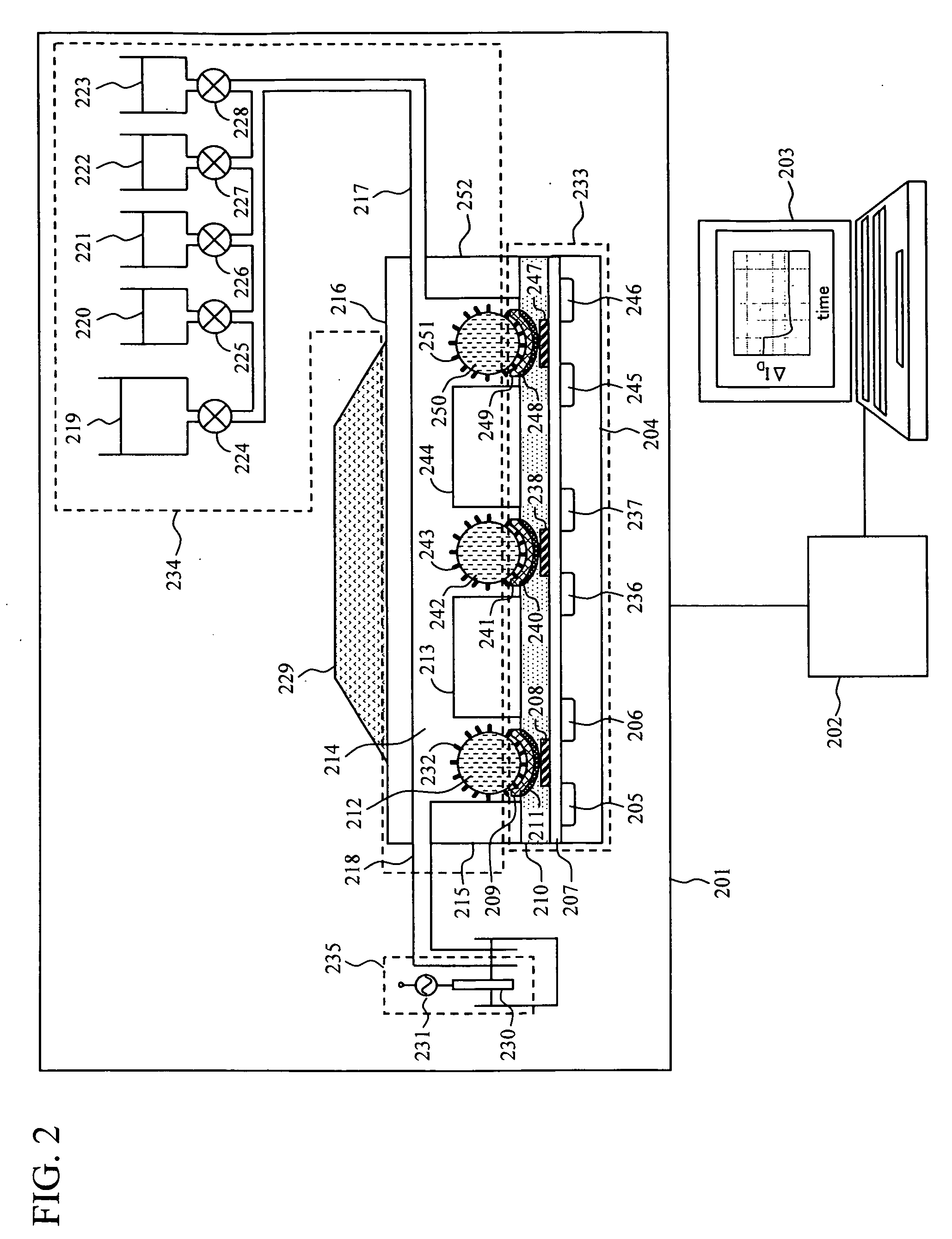
[0026]FIG. 2 shows an example of a system configuration of a FET-based DNA sequencer according to the present invention. The system is configured of a measuring unit 201, a signal processing circuit 202, and a data processing device 203. Further, the measuring unit 201 has four structural components including: a FET sensor unit 233, a chamber unit 234, a fine particle control unit 229, and a reference electrode unit 235. Details of these components will be described below.

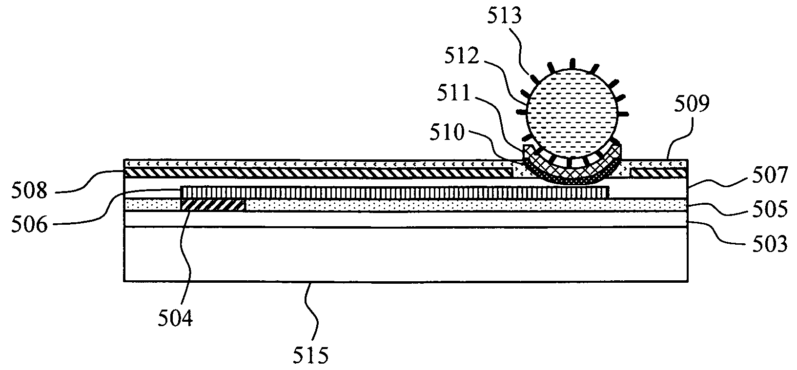
[0027]The FET sensor unit 233 has multiple FETs formed on a silicon substrate 204, includes multiple combinations of: a source 205; a drain 206; a metal electrode 209 formed on an adhesive layer 211 connected to a gate insulating film 207 through a conductive wiring 208; a source 236; a drain 237; a metal electrode 241 formed on an adhesive layer 240 connected to the gate insulating film 207 through a conductive wiring 238; a source 245; a drain 246; and a metal electrode 249 formed on an adhesive layer 248 connect...

second embodiment

[0048]In the second embodiment, a magnetic field generator was used as a means for controlling the position of the fine particle. The general configuration of the system is equivalent to that shown in FIG. 2. In the second embodiment, a strong magnet was used as the magnetic field generator for the fine particle control unit 229, and magnetic beads of 200 μm in diameter were used for the fine particles 212, 242 and 250. A preparation method for the fine particles 212, 242 and 250 having the DNA molecules 232, 243 and 251 immobilized thereon, a method for settlement of the fine particles 212, 242 and 250 in the wells, and an extension reaction method are equivalent to those of the first embodiment. Description will be given below with regard to a solution change and a interfacial potential detection method, which are different from the first embodiment.

[0049]At the time of the solution change using the solution injection port 217 and the solution ejection port 218, for purposes of mo...

third embodiment

[0051]Description will be given with reference to FIG. 2, as in the case of the first and second embodiments. In the third embodiment, temperature control is used to control the position of the fine particle for nucleotide sequence determination. To this end, a Peltier element for the temperature control is disposed in the fine particle control unit 229. Other structural components are equivalent to those of the first embodiment. Incidentally, in the third embodiment, the Peltier element is used; however, anything other than the Peltier element may also be used, as long as it is a system for temperature control. Also, a specific sequence determination method is equivalent to the first embodiment, except for a fine particle manipulation method for the interfacial potential detection method.

[0052]For the interfacial potential detection, the Peltier element of the fine particle control unit 229 was used to set the temperature in the solution tank 214 at 5 degrees. This suppresses the B...


PUM

PropertyMeasurementUnit
diameteraaaaaaaaaa
diameteraaaaaaaaaa
wavelengthsaaaaaaaaaa

Abstract

The present invention provides a DNA sequencer using a FET sensor, capable of long-base decoding. Target DNAs are immobilized on the surfaces of spherical fine particles, the fine particles are disposed in the vicinity of metal electrodes each of which is connected electrically to a corresponding one of conductive wirings of the FET sensor and partly has a spherical surface capable of contacting with the fine particles, and the FET sensor detects a change in interfacial potential incident to an extension reaction of DNA molecules containing a hybridization of the target DNA and probe DNA.

Description

CLAIM OF PRIORITY[0001]The present application claims priority from Japanese application JP 2007-164231 filed on Jun. 21, 2007, the content of which is hereby incorporated by reference into this application.BACKGROUND OF THE INVENTION[0002]1. Field of the Invention[0003]The present invention relates to a measuring system for making a measurement on a biological substance, such as DNA (deoxyribonucleic acid) or RNA (ribonucleic acid), as unmodified, and a measuring method using the same, and more particularly to a measuring system and method using a field effect transistor (FET).[0004]2. Description of the Related Art[0005]Recent marked advances in nucleotide sequence analysis technology have led to determination of a reference sequence for a whole human genome, thus enabling a comparison for determining directly the dissimilarity in genes between individuals. As for a disease-related gene in particular, gene analysis using SNPs is used to narrow down a potential region as a candidat...

Claims


Application Information

Patent Timeline
Patent Type & Authority Applications(United States)
IPC IPC(8): C12Q1/68
CPCC12Q1/6825C12Q1/6869C12Q2565/518C12Q2565/607G01N27/4145
Inventor HAGA, TAKANOBUKAMAHORI, MASAOSAKAI, TOMOYUKIISHIGE, YU
Owner HITACHI LTD
Why Eureka
Try Eureka