Image forming apparatus

a technology of image forming apparatus and forming chamber, which is applied in the direction of electrographic process apparatus, instruments, optics, etc., can solve the problems of complex charge control of toner, large apparatus, and high surface area, and achieve suppression of image density defects, fogging, and toner scattering.

Active Publication Date: 2009-01-01
KYOCERA DOCUMENT SOLUTIONS INC
View PDF5 Cites 15 Cited by
  • Summary
  • Abstract
  • Description
  • Claims
  • Application Information

AI Technical Summary

Benefits of technology

[0022]An object of the present invention is to provide an image forming apparatus capable of maintaining stable performances over a long term by suppressing image density defects, fogging, toner scattering, ghost phenomenon and the like.

Problems solved by technology

This method has an advantage of being fast, but has a disadvantage of enlarging the apparatus since electrophotographic processing members (image forming units) of the respective colors have to be arranged side by side.
However, with this technology, the charge control of the toner is complicated and a high surface potential and a large developing electric field need to be applied to the photoconductor.
Further, since it is difficult to remove the toner on the donor roller unused for image development, if a toner consumed region and a toner nonconsumed region are formed on the donor roller, an adhering state of the toner and a potential difference of the toner on this donor roller vary.
Thus, there is a problem of the occurrence of a phenomenon in which part of a previously developed image appears as a residual image (ghost) during the next image development, so-called a history phenomenon.
However, fogging occurs if an alternating voltage is too high, whereas the effect of pulling back the toner unused for image development is reduced if the alternating voltage is low.
Thus, if durability is also considered, it is difficult to ensure optimal values.
Since the respective output voltages of the first and second bias power supplies 911, 912 relate to controls of the releasability of toner on the developing roller unused for image development, the toner thin layer formation and the toner developability between the magnetic roller and the developing roller, it is not easy to set the potential difference between the magnetic roller and the developing roller to a desired potential difference while balancing voltages suitable for these controls and the potential difference between the magnetic roller and the developing roller.
Specifically, if the toner particles are selectively transferred, the toner charge distribution in the two-component developer broadens, wherefore it becomes difficult to stably form the thin toner layer (image forming operation; printing operation) on the developing roller over a long term.

Method used


Image

  • Image forming apparatus
  • Image forming apparatus
  • Image forming apparatus

Examples


first embodiment

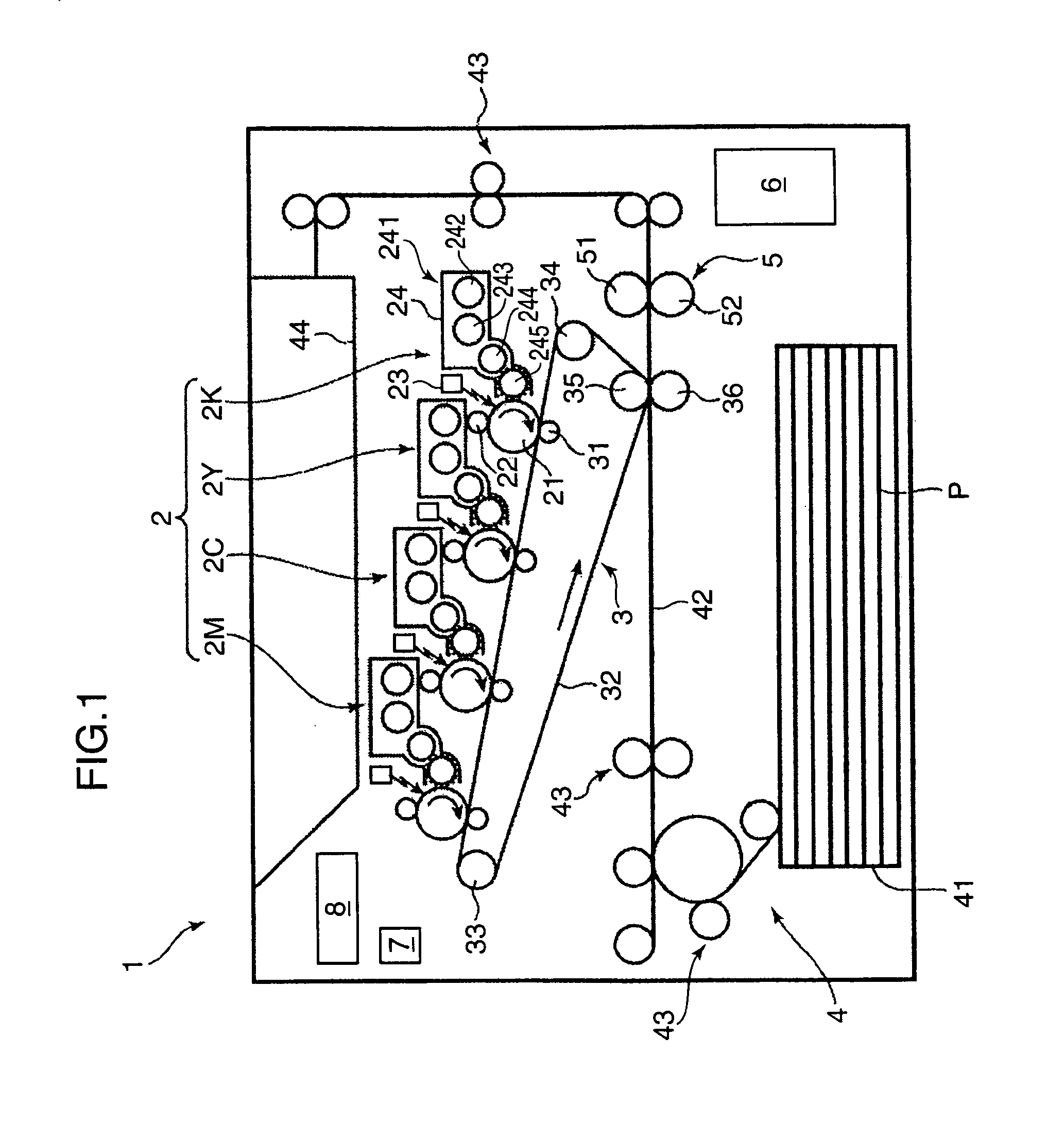
[0040]Hereinafter, printers as examples of an image forming apparatus according to the present invention are described with reference to the accompanying drawings. FIG. 1 is a schematic construction diagram of an example of a printer according to a first embodiment. As shown in FIG. 1, the printer 1 is a so-called tandem image forming apparatus and image forming units 2M, 2C, 2Y and 2K of different colors, i.e. magenta (M), cyan (C), yellow (Y) and black (K) are arranged side by side in a printer main body.

[0041]The image forming units 2M, 2C, 2Y and 2K (an assembly of these is called an “image forming assembly 2”) are for forming (printing) a color image on a sheet and are each provided with a photoconductive drum 21 (latent image bearing member) made of, for example, amorphous silicon (a-Si), a charger 22, an exposing device 23 and a developing device 24 arranged around this photoconductive drum 21.

[0042]The charger 22 uniformly charges the outer surface of the photoconductive dru...

second embodiment

[0099]In a second embodiment, the above printer 1 was constructed (set) to satisfy the following conditions (development conditions). Specifically, an a-Si drum made of the above a-Si photoconductor was used as the photoconductive drum 21; the photoconductive drum diameter was set to 30 mm, the developing roller diameter to 20 mm and the magnetic roller diameter to 25 mm.

[0100]The circumferential speeds of these were as follows.

Photoconductive drum 21:300 mm / secDeveloping roller:450 mm / secMagnetic roller:675 mm / sec.

[0101]The developing roller 245 used had the outer surface thereof made of an aluminum base material and had an alumite processing applied to the outer surface of the aluminum base material (coated with the silicon modified urethane resin in the first embodiment). A gap (spacing) between the magnetic roller 244 and the developing roller 245 was 350 μm.

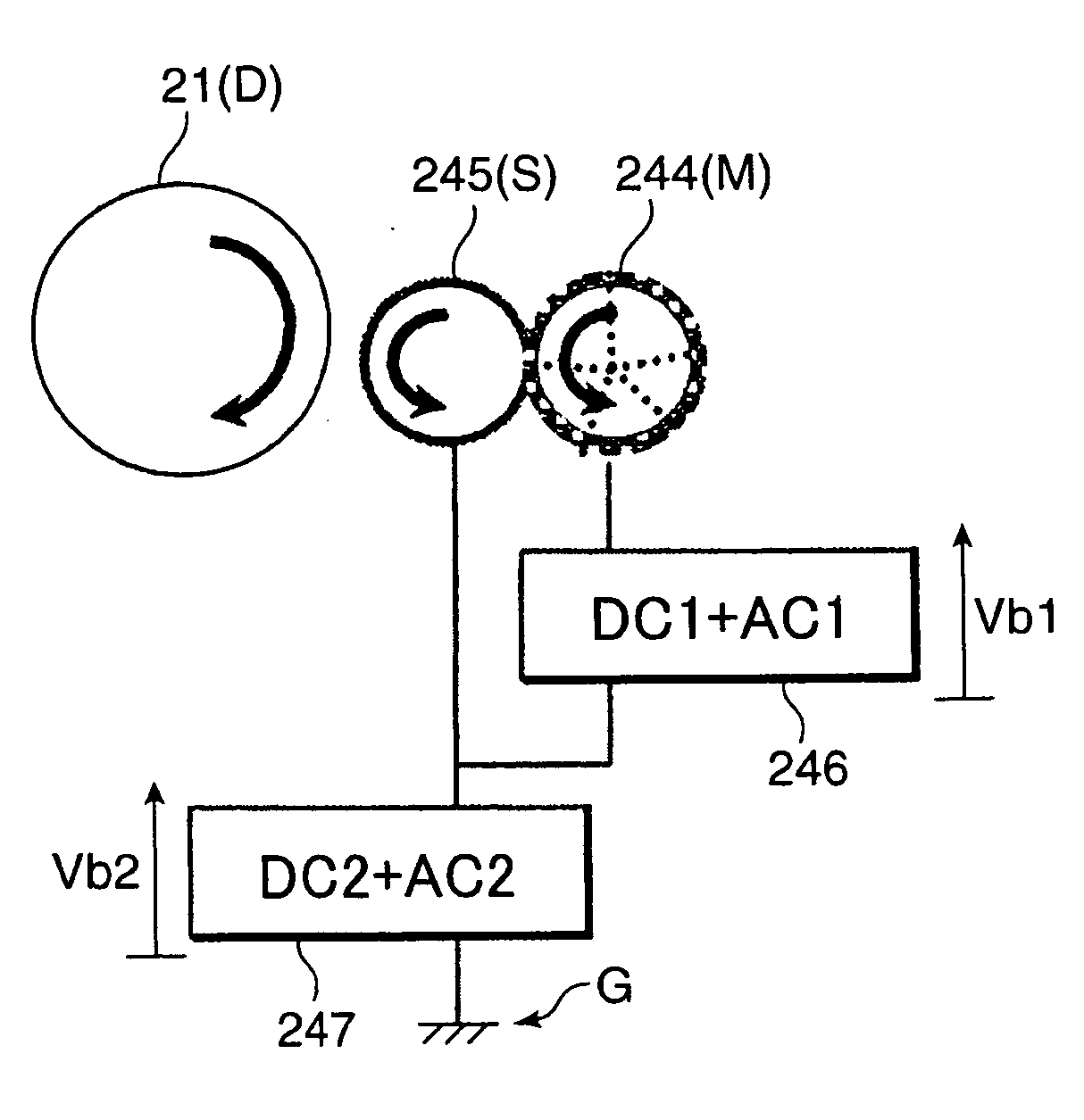
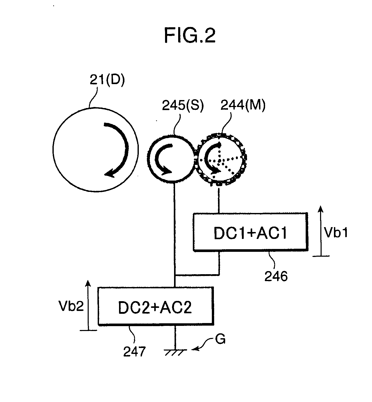
[0102]Bias voltages applied to the magnetic roller 244 and the developing roller 245 were as follows. Further, the wavefor...

third embodiment

[0112]Although Duty(slv)=50% and Duty(mag)=65% in the second embodiment, the setting is not limited thereto and any setting to satisfy the above condition, i.e. 100(%)−Duty(mag)1), (AC2) in this case are shown in FIG. 9.

[0113]In this case as well, it was empirically found that the half width difference of the charge number distribution of toner could be set to 0.8 (10−10 C / m) or smaller or that the half width difference and the peak position difference could be respectively set to 0.8 (10−10 C / m) or smaller and 1.0 (10−10 C / m) or smaller.

[0114]Results in the case of forming images on sheets using the image forming apparatuses according to these first to third embodiments are summarized in a table shown in FIG. 5. FIG. 5 shows experimental results obtained for the first to third embodiments as Examples 1 to 3. Other examples according to the present invention are shown as Examples 4 to 8. In this table are also shown Comparative Examples 1 to 4 according to prior arts. Specific evalu...


PUM


Abstract

An image forming apparatus uses a two-component developer containing a toner and a carrier. The apparatus has a latent image bearer for bearing an electrostatic latent image. A toner bearer bears the toner to be conveyed to a development region to develop the electrostatic latent image. A developer bearer bears the two-component developer and supplies the toner to the toner bearer. A regulator sets the thickness of a toner layer carried on the toner bearer to 6 μm to 15 μm and sets a difference between a half width of a first toner charge number distribution as a number distribution of the charge amount of the toner carried on the toner bearer and that of a second toner charge number distribution as a number distribution of the charge amount of the toner in the two-component developer carried on the developer bearer to 0.8 (10−10 C/m) or smaller.

Description

BACKGROUND OF THE INVENTION[0001]1. Field of the Invention[0002]The present invention relates to an electrophotographic image forming apparatus such as a copier, a printer, a facsimile machine or a complex machine and particularly to an image forming apparatus employing a non-contact developing method for developing an electrostatic latent image using a two-component developer, in which a nonmagnetic toner is charged by a magnetic carrier, by holding only the charged toner on a developing roller and transferring the toner toward the electrostatic latent image.[0003]2. Description of the Related Art[0004]Conventionally, development by a non-contact developing method with the use of a one-component developer has been considered for image forming apparatuses such as copiers, printers, facsimile machine and complex machines. In recent years, with the speeding up of printing, consideration has been made about image development for a high-speed image forming method, particularly image dev...

Claims


Application Information

Patent Timeline
Patent Type & Authority Applications(United States)
IPC IPC(8): G03G15/08
CPCG03G15/065G03G2215/0634G03G15/0812
Inventor FUJISHIMA, MASASHISAKATA, SHOICHIKOBAYASHI, KIYOTAKAMORI, YUKIHIRO
Owner KYOCERA DOCUMENT SOLUTIONS INC
Why Eureka
Try Eureka