Sealed battery and manufacturing method therefor

Active Publication Date: 2009-01-01
SANYO ELECTRIC CO LTD
View PDF4 Cites 58 Cited by
  • Summary
  • Abstract
  • Description
  • Claims
  • Application Information

AI Technical Summary

Benefits of technology

[0049]Since the adhesive will be soft and therefore prone to change its shape, it will be liable to protrude out from the insulating tape when pressure is applied with the bolt poles during resistance welding. However, with a and H in the relation a<H, the adhesive's thickness a will be lower than the height H of the flat-surfaced salient and therefore the adhesive will not cover the flat-surfaced salient during res

Problems solved by technology

However, when discharge of high output is implemented, large current will flow in the battery, and as a result there will be large heat-up due to contact resistance between the substrates and the collectors, which are the generation elements.
Also, in order to effect low resistance, the material used for the negative electrode assembly of a lithium ion secondary battery is copper or copper alloy, which however have the characteristics of low electrical resistance and high thermal conductivity, so that extremely large amounts of energy are required in order to weld them.
There also exist the problems that when copper or copper alloy is laser-welded, the weldability varies greatly depending on the condition of the surfaces, and that the occurrence of spatter is unavoidable, as in laser welding of other materials.
With ultrasonic welding too, large amounts of energy are required because the thermal conductivity of the copper or copper alloy welded material is high.
Further, with resistance welding, due to the copper or copper alloy welded material having low electrical resistance and high thermal conductivity there exist the problems that large current needs to be input in a short time, that fusion-joining of the collectors and the bolt poles, which are of the same material as the collectors, sometimes occurs during welding, and that melting or spark generation may occur at places other than the welds.
Thus, the three welding methods have their merits and drawbacks.
Moreover, when the welding energy is rendered large for resistance welding, occurrence of spatter increases, as does the probability of internal short circuits resulting from movement of the spatter into the interior of the sealed battery's electrode assembly.
Further, during resistance welding, occurrence of spatter increases.
If resistance welding is performed in such a state with the thermodeposited resin itself, or the adhesive, protruding out to the weld, then the thermodeposited resin itself, or the adhesive, may explosively combust.
Copper and copper alloy are the items with the lowest electrical resistance and the highest thermal conductivity among the commonly-used conductive metals, and therefore generate large amounts of spatter during resistance welding, which requires large current to be passed.
If the thickness of the insulating seal material were less than 0.1 times the height of the protuberances, the situation would be essentially the same as that where there is no insulating seal material and would be undesirable since splashing of the spatter to the exterior could not be inhibited and as a result internal short-circuits would increase.
Also, if the thickness of the insulating seal material ex

Method used


Image

  • Sealed battery and manufacturing method therefor
  • Sealed battery and manufacturing method therefor
  • Sealed battery and manufacturing method therefor

Examples


first example

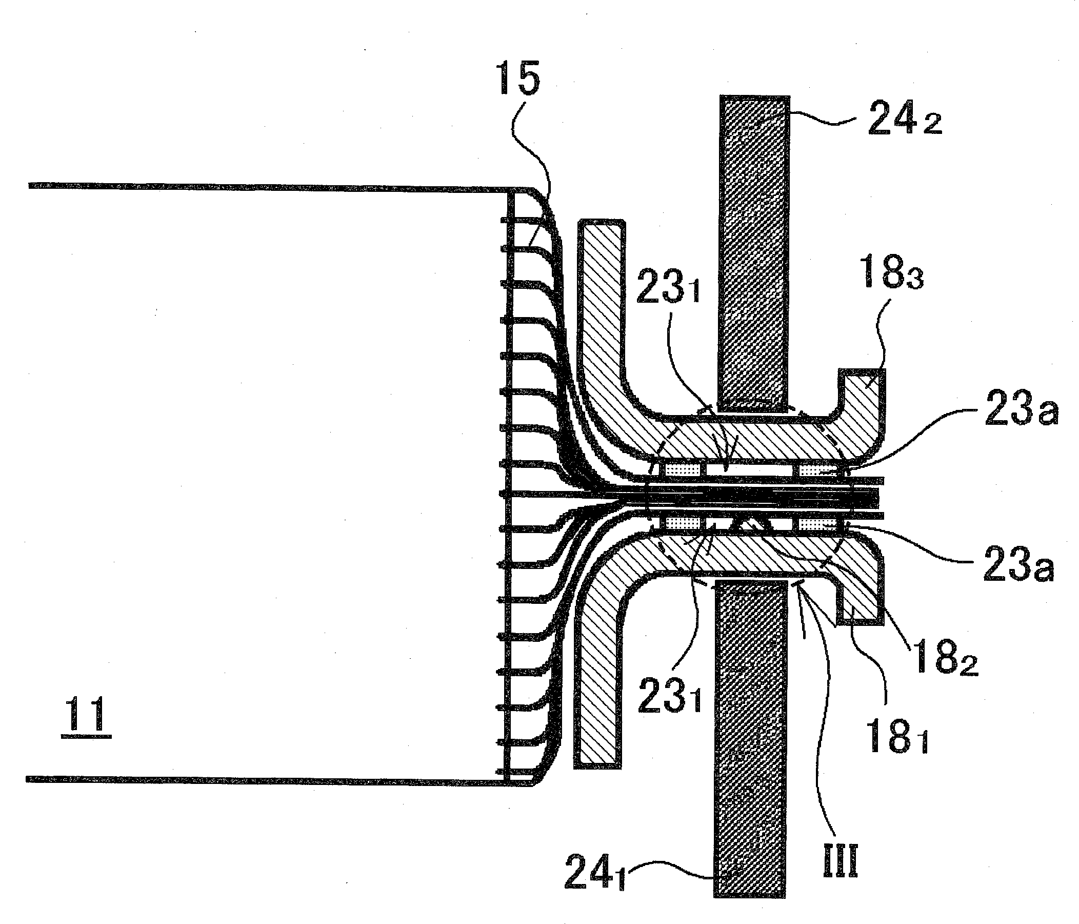
[0071]For the prismatic nonaqueous electrolyte secondary battery 10 of the first working example, an item was used in which a protuberance 182 (height h=0.8 mm, base portion diameter W=2 mm) acting as a projection was formed on the central portion of the negative electrode collector 181. For the insulating seal material, tape 23a (thickness L=0.1 mm) made of thermodeposited resin and with an opening 231 (circular, diameter A=6 mm) in the central portion was used. The thermodeposited resin tape 23a used consisted of multilayer film including polyolefin-based thermodeposited resin layers.

[0072]First of all, the negative electrode substrate exposed portions 15, made of copper, were bunched together, and thermodeposited resin tapes 23a were placed above and below the resulting bunch in such a manner that the centers of the openings 231 formed in the thermodeposited resin tapes 23a coincided, the bunch was disposed so that the protuberance 182 on the copper negative electrode collector 1...

second working example

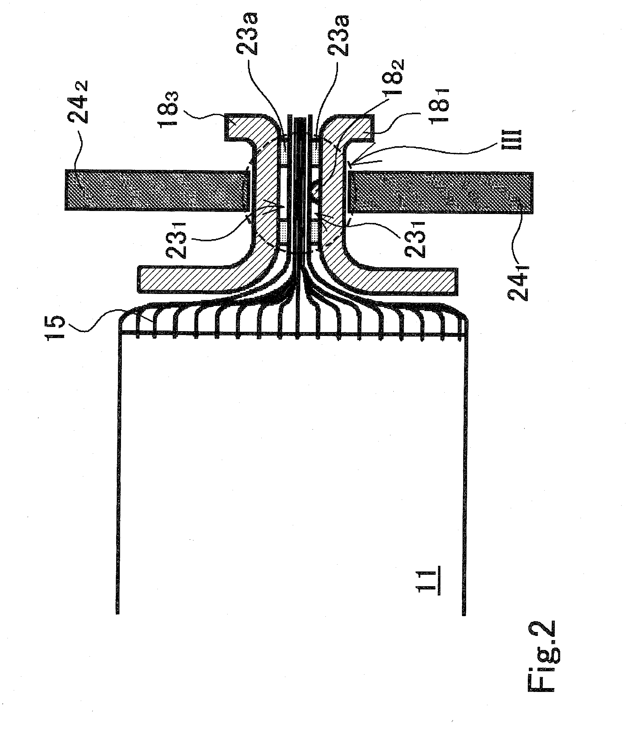
[0082]In the prismatic nonaqueous electrolyte secondary battery 10 of the first working example, resistance welding was performed using a protuberance 182 formed in the central portion of the negative electrode collector 181 and an opening 231 formed in the central portion of the thermodeposited resin tape 23a, as shown in FIGS. 2 and 3. However, since the resistance welding bolt poles 241 and 242 will become hot, especially if resistance welding is performed continuously, the thermodeposited resin tape 23a itself could soften before the resistance welding current is applied. If resistance welding is performed under such conditions, the thermodeposited resin tape 23a itself could protrude out toward the weld, as shown in FIG. 5, due to the negative electrode collector 18i and negative electrode collector receiving part 183 being pushed together from both sides by the bolt poles 241 and 242 during the resistance welding. Under such conditions the thermodeposited resin could explosive...

third working example

[0087]Although thermodeposited resin tape 23a was used as the insulating seal material in the first and second working examples, it is alternatively possible to use adhesive insulating tape. The structure of a resistance weld in the prismatic battery of a third working example, which uses adhesive insulating tape 23b as the insulating seal material, will now be described using FIGS. 8 to 10. The elements in FIGS. 8 to 10 that are structurally identical to those in FIGS. 6 and 7 are assigned the identical reference numerals and detailed descriptions thereof are omitted.

[0088]The sole respect in which the structure of the weld in the third working example differs from that of the weld in the second working example is that whereas thermodeposited resin tape 23a was used as the insulating seal material in the second working example, adhesive insulating tape 23b is used in the third working example; the other structural aspects are essentially identical. For such adhesive insulating tape...


PUM

PropertyMeasurementUnit
Thicknessaaaaaaaaaa
Diameteraaaaaaaaaa
Adhesivityaaaaaaaaaa

Abstract

The present invention's manufacturing method for a sealed battery includes: a process whereby a sealed battery application electrode assembly 11 is formed that has multiple positive electrode substrate exposed portions 14 at one end and multiple negative electrode substrate exposed portions 15 at the other end; a process whereby the negative electrode collector 181 and negative electrode collector receiving part 183 are brought against both surfaces of the part to be welded on at least the negative electrode substrate exposed portions 15, with tape 23a constituted of thermodeposited resin and having an opening 231 in the center being interposed; and a process whereby resistance welding is effected by passing current between the negative electrode collector 181 and negative electrode collector receiving part 183 positioned at the two sides.

Description

TECHNICAL FIELD[0001]The present invention relates to a sealed battery and manufacturing method therefor. More particularly it relates to a sealed battery which has exposed portions of positive electrode substrates at one end and of negative electrode substrates at the other, which is high-reliability, and in which, since spatter occurring when the collectors are resistance welded to the substrates is prevented from moving into the electrode assembly interior, few internal short-circuits occur; and to a manufacturing method therefor.RELATED ART[0002]Curbs on emissions of carbon dioxide and other substances have been strengthened against a background of growing movements for environmental protection, and in the automobile world there is now vigorous development of electric vehicles (EVs) and hybrid electric vehicles (HEVs) alongside vehicles using fossil fuels such as gasoline, diesel oil and natural gas. In addition, the soaring prices of fossil fuels in recent years has acted to sp...

Claims


Application Information

Patent Timeline
IPC IPC(8): H01M2/08H01M4/82H01M50/528H01M50/417
CPCH01M2/1653H01M2/263Y10T29/49108H01M4/661H01M10/05H01M2/266Y02E60/10H01M50/417H01M50/183
Inventor NANSAKA, KENJITANIGUCHI, YASUTOMOYAMAUCHI, YASUHIRONOHMA, TOSHIYUKIINAGAKI, KENJIYOSHIDA, SATOSHIKONDOU, TAKASHI
Owner SANYO ELECTRIC CO LTD
Why Eureka
Try Eureka