Non-Etched Flat Polarization-Selective Diffractive Optical Elements

a diffractive optical element and flat polarization technology, applied in the field of diffractive optical elements, can solve the problems of low cost, inconvenient use, and inability to meet the needs of many applications, and achieve the effect of low cost and easy formation with precision

Inactive Publication Date: 2009-01-08
JDS UNIPHASE CORP
View PDF29 Cites 67 Cited by
  • Summary
  • Abstract
  • Description
  • Claims
  • Application Information

AI Technical Summary

Benefits of technology

[0010]The instant invention relates to a method of forming diffraction gratings and / or holograms with thin liquid crystal polymer layers. In one embodiment a thin liquid crystal polymer is formed on an alignment layer, which has been irradiated with linearly polarized light at non-normal incidence through a photo-mask. In this embodiment, the photo-mask is patterned such that the light is incident on different areas of the alignment layer with different energy densities. Advantageously, each region of the alignment layer irradiated with a different energy density provides a different out-of-plane tilt angle in the overlying region of the liquid crystal polymer coated thereon. Accordingly, a hologram having a plurality of tilt-angles between zero and ninety degrees is easily formed with precision. As a result, relatively complex hologram structures are easily designed for a wide range of applications. In addition, since the liquid crystal polymer film is coated on a single substrate and patterned without etching and / or molding, the resulting holograms are flat and can be provided at low cost.

Problems solved by technology

Accordingly, these types of LC holograms are typically only useful in optical systems and instrumentation where the light sources are polarized.
Although programmable thin holograms encoded onto LC / SLMs are very versatile, these active components are not cost effective for many applications.
Unfortunately, since the alignment of the liquid crystal is related to an average of different regions it cannot be patterned with precision and thus, is not suitable for many applications.
Unfortunately, the etching and / or molding processes used to form these diffractive optical elements are relatively complex and time consuming.
In addition, the surface relief structure generally requires complex optical thin-film coating processes to protect the delicate structures.

Method used


Image

  • Non-Etched Flat Polarization-Selective Diffractive Optical Elements
  • Non-Etched Flat Polarization-Selective Diffractive Optical Elements
  • Non-Etched Flat Polarization-Selective Diffractive Optical Elements

Examples


Embodiment Construction

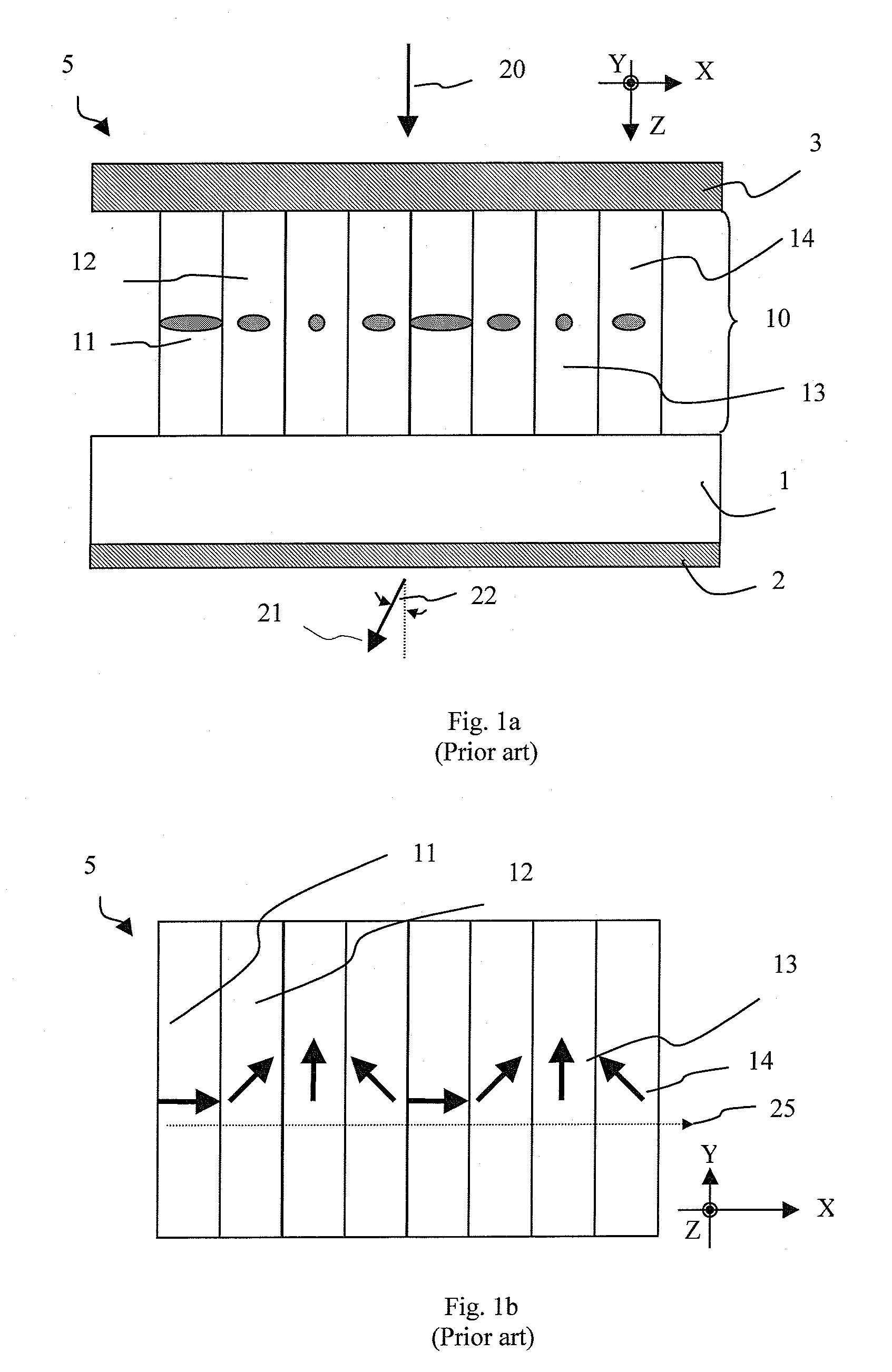
[0063]A prior-art thin liquid crystal (LC) hologram structure is illustrated in FIG. 1, which is a thickness cross-sectional view along the grating vector. The grating vector is the plane where the light is dispersed by diffraction effect. It is also the pixelation direction for a 1D grating or hologram. The hologram 5 includes a substrate 1, onto which an array of pixels 10 having varying azimuthal LC director orientations is disposed. Four discrete azimuthal LC director orientations are shown as 11, 12, 13 and 14. More specifically, the projection of the LC index indicatrix onto the plane of drawing (XZ-plane) is shown. Pixel 11 has its projected director aligned parallel to the X-axis, whereas pixel 13 has its projected director aligned parallel to the Y-axis. The other two states, pixels 12 and 14 have their projected directors contained within the XY plane but non-parallel to both the X- and Y-axes. The hologram element 5 also includes AR coating stacks 2 and 3 to aid transmiss...


PUM

PropertyMeasurementUnit
deflection angleaaaaaaaaaa
tilt-anglesaaaaaaaaaa
out-of-aaaaaaaaaa

Abstract

A polarization-selective diffractive optical element includes a liquid crystal polymer film supported by a substrate. The liquid crystal polymer film includes an array of pixels, each pixel encoded with a fixed liquid crystal director such that each liquid crystal director is aligned in a common plane perpendicular to the liquid crystal polymer film and provides a predetermined pattern of out-of-plane tilts. A size of the pixels in the array and the predetermined pattern are selected such that the liquid crystal polymer film forms a phase hologram for diffracting light polarized parallel to said common plane and a zeroth order diffraction grating for light polarized perpendicular to the said common plane. The non-etched and flat phase hologram is suitable for a wide range of applications.

Description

CROSS-REFERENCE TO RELATED APPLICATIONS[0001]This application claims priority from U.S. Provisional Application No. 60 / 947,690, filed Jul. 3, 2007, Which is hereby incorporated by reference.MICROFICHE APPENDIX[0002]Not Applicable.TECHNICAL FIELD[0003]The present application relates generally to diffractive optical elements, and in particular to non-etched and flat polarization-selective diffractive optical elements.BACKGROUND OF THE INVENTION[0004]Diffraction gratings and more complex thin holograms, encoded onto programmable liquid crystal (LC)-based spatial light modulators (SLMs), have been actively researched as a way to alter the wavefront of an optical beam. For example, these LC / SLMs may be used for adaptive-optic phase correction, in a synthetic phase array, or in a telecommunication beam steering switch. The LC / SLMs are based typically on either a transmissive or reflective type micro-display panel in order to provide the small pixel pitch requirement. LCs with both in-plan...

Claims


Application Information

Patent Timeline
Patent Type & Authority Applications(United States)
IPC IPC(8): G02F1/13G03H1/02G11B7/135
CPCG02B5/1871G02B5/3016G02B5/32G02F1/13342G02F1/133753G11B2007/0006G03H2240/11G03H2240/23G03H2250/38G11B7/1353G11B7/13925G02F2203/07G02B5/30G02F1/1337
Inventor TAN, KIM LEONGSHEMO, DAVID M.
Owner JDS UNIPHASE CORP
Why Eureka
Try Eureka