Thermally Stable Multilayer Mirror for the EUV Spectral Range

a multi-layer mirror and spectral range technology, applied in the field of thermodynamic stability multi-layer mirrors, can solve the problems of significant reduction of reflection, degradation of such multi-layer mirrors, and impairment of the function of an optical system based on mo/si multi-layer mirrors, and achieve the effects of reducing reflection and/or period thickness, reducing contamination, and high long-term stability

Inactive Publication Date: 2009-01-08
FRAUNHOFER GESELLSCHAFT ZUR FOERDERUNG DER ANGEWANDTEN FORSCHUNG EV
View PDF14 Cites 10 Cited by
  • Summary
  • Abstract
  • Description
  • Claims
  • Application Information

AI Technical Summary

Benefits of technology

[0012]In one aspect, the invention specifies a multilayer mirror for the EUV spectral range that is distinguished by a high thermal stability, in particular a comparatively high long-term stability, wherein the production outlay is preferably intended to be comparatively low.
[0014]By virtue of the fact that at least in each case one layer of the layer pairs is a silicon boride layer or a molybdenum nitride layer, the interdiffusion at the interfaces between the first layers and the second layers of the layer pairs is reduced, in particular, at high operating temperatures. The long-term thermal stability and the radiation stability of the multilayer mirrors are thereby advantageously improved by comparison with conventional multilayer mirrors.
[0020]This is advantageous, particularly when the multilayer mirror is provided for the reflection of radiation whose angle of incidence varies over the surface of the multilayer mirror. In this case, the first and / or the second layer of the layer pairs advantageously has a layer thickness gradient, that is to say that the thickness of the first and / or second layers varies in a lateral direction. The production of such layer thickness gradients is associated with a lower outlay in the case of a layer sequence in which the individual layers are at least about 2 nm thick than in the case of layer sequences having barrier layers in which at least the barrier layers have thicknesses in the sub-nanometer range.
[0027]A multilayer mirror according to the invention has the advantage, in particular, of a high long-term stability at temperatures of more than 300° C., in particular in the temperature range from 300° C. to 500° C. By way of example, a multilayer mirror according to embodiments of the invention still has no significant reduction of the reflection and / or period thickness even after an operating time of 100 h at a temperature of approximately 500° C.
[0028]In a preferred configuration of the invention, the multilayer mirror is heated to a high operating temperature, for example, to 300° C. or more, preferably even to 400° C. or more, in order to reduce the deposition of contaminants on the multilayer mirror. For this purpose, a heating device can be provided, which is preferably fitted to a substrate of the multilayer mirror. This is advantageous, in particular, in the case of a multilayer mirror that is arranged in the vicinity of an EUV radiation source, since the multilayer mirror in this case could be contaminated by a target material used in the EUV radiation source, for example, lithium, the material being excited to emit EUV radiation by means of a laser beam, as a result of which contamination the reflection would be impaired. By heating the multilayer mirror to an operating temperature of preferably approximately 400° C., for example, the adhesion coefficient of lithium on a surface of the multilayer mirror is advantageously reduced in such a way that the reflection is not significantly impaired even after an operating time of 100 hours or more.

Problems solved by technology

Therefore, at high application temperatures, there is the risk of degradation of such multilayer mirrors, which significantly reduces the reflection.
The function of an optical system based on Mo / Si multilayer mirrors can be considerably impaired or even completely destroyed by such degradation processes.
In particular, it is difficult to deposit a layer sequence with such thin barrier layers on curved substrates.

Method used


Image

  • Thermally Stable Multilayer Mirror for the EUV Spectral Range
  • Thermally Stable Multilayer Mirror for the EUV Spectral Range
  • Thermally Stable Multilayer Mirror for the EUV Spectral Range

Examples


Embodiment Construction

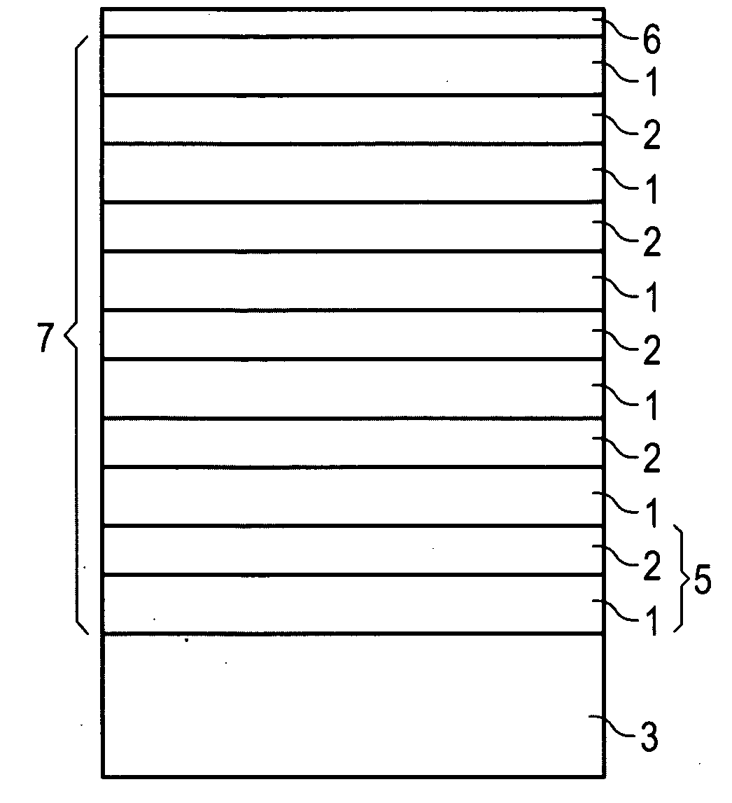
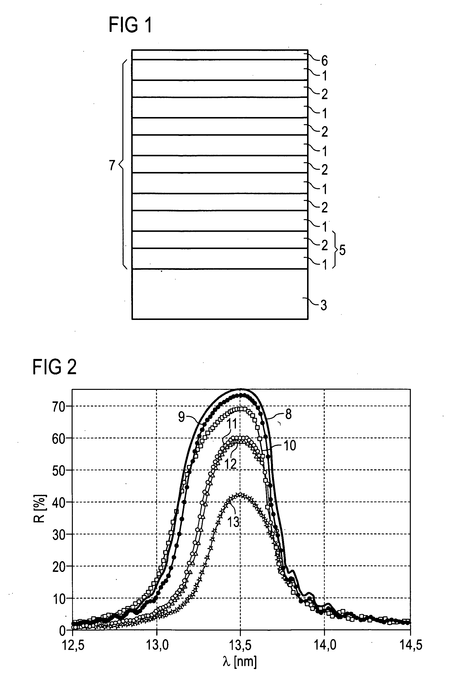
[0034]In the multilayer mirror according to an embodiment of the invention as illustrated in FIG. 1, a layer sequence 7 containing a number of layer pairs 5 is applied to a substrate 3. In order to simplify the illustration, only four layer pairs 5 are illustrated. A preferred number of layer pairs 5 is 30 to 100.

[0035]The layer pairs 5 in each case include of a first layer 1 composed of a first material and a second layer 2 composed of a second material. In this case, at least one of the materials is a silicon boride or a molybdenum nitride.

[0036]In one preferred embodiment of the invention, the first material is a silicon boride, for example, SiB4 or SiB6.

[0037]In a further preferred embodiment of the invention, the first material is silicon and the second material is a molybdenum nitride, for example, MoN.

[0038]The substrate 3 is, for example, a semiconductor substrate, in particular, composed of silicon or SiC, or a substrate composed of a glass or a glass ceramic, in particular...


PUM


Abstract

A multilayer mirror includes a layer sequence arranged on a substrate and a plurality of layer pairs. Each layer pair includes a first layer composed of a first material and a second layer composed of a second material. The first layers and the second layers each have a thickness of more than 2 nm, and the first material or the second material is a silicon boride or a molybdenum nitride.

Description

[0001]This application is a continuation of co-pending International Application No. PCT / DE2007 / 000126, filed Jan. 24, 2007, which designated the United States and was not published in English, and which claims priority to German Application No. 10 2006 006 283.3 filed Feb. 10, 2006, both of which applications are incorporated herein by reference.TECHNICAL FIELD[0002]The invention relates to a thermally stable multilayer mirror for the extreme ultraviolet spectral range (EUV) and the use of the mirror.BACKGROUND[0003]Reflective optical components for use in the extreme ultraviolet spectral range (EUV), which encompasses the wavelength range from approximately 10 nm to approximately 50 nm, can be realized with multilayer mirrors containing a generally periodic layer sequence comprising a plurality of layer pairs. A layer pair generally contains two layers composed of different materials, which should have a maximum difference in their optical constants in the wavelength range provide...

Claims


Application Information

Patent Timeline
Patent Type & Authority Applications(United States)
IPC IPC(8): G02B5/08
CPCB82Y10/00G02B5/0891G21K2201/067G21K2201/061G21K2201/064G21K1/062G02B5/00G02B5/08G02B6/08G21K1/06
Inventor FEIGL, TORSTENBENOIT, NICOLASYULIN, SERGIYKAISER, NOBERT
Owner FRAUNHOFER GESELLSCHAFT ZUR FOERDERUNG DER ANGEWANDTEN FORSCHUNG EV
Why Eureka
Try Eureka