Preparation of Gas Diffusion Layer for Fuel Cell

a fuel cell and gas diffusion technology, applied in cell components, electrochemical generators, electrode manufacturing processes, etc., can solve the problems of difficult construction of gas diffusion layer and catalyst layer, inability to use common coating methods, and inability to effectively discharge water generated by hydrogen ions with oxygen in air, etc., to achieve uniform electronic conductivity, efficient electrical connection, and sufficient porosity

Inactive Publication Date: 2009-01-08
LEE EUN SOOK +7
View PDF8 Cites 24 Cited by
  • Summary
  • Abstract
  • Description
  • Claims
  • Application Information

AI Technical Summary

Benefits of technology

[0069]A gas diffusion layer prepared using a method of preparing a gas diffusion layer according to the present invention has sufficiently uniform electronic conductivity to be efficiently electrically connected to an external electrical circuit, and at the same time, has enough porosity to permit easy access of fuel and a reaction gas to a catalyst layer.
[0070]Moreover, according to a method of preparing a gas diffusion layer of the present invention, a gas diffusion layer can be easily prepared in various shapes according to the needs of a user since it is easy to modi

Problems solved by technology

However, since a methanol solution is hydrophilic and a carbon dioxide gas is hydrophobic, it is very difficult to construct a gas diffusion layer and a catalyst layer such that inflow of fuel and discharge of products are efficiently performed.
Meanwhile, with respect to an air electrode, efficient discharge of water generated by reaction of hydrogen ions with oxygen in air is the most important issue.
However, in a conventional method of preparing a gas diffusion layer, a carbon paste is too viscous to be coated using a common coating method.
A carbon paste with such a high viscosity is not properly coated on a substrate, such as a carbon paper, and is not adhered to a substrate until a mechanical force is applied thereto.
Thus, it is difficult to coat a carbon paste on a substrate.
According to the method, a substrate, such as a carbon paper or a carbon felt, is pressed to about 40-60% of its original thickness, and thus, suffers

Method used


Image

  • Preparation of Gas Diffusion Layer for Fuel Cell
  • Preparation of Gas Diffusion Layer for Fuel Cell
  • Preparation of Gas Diffusion Layer for Fuel Cell

Examples


example 1

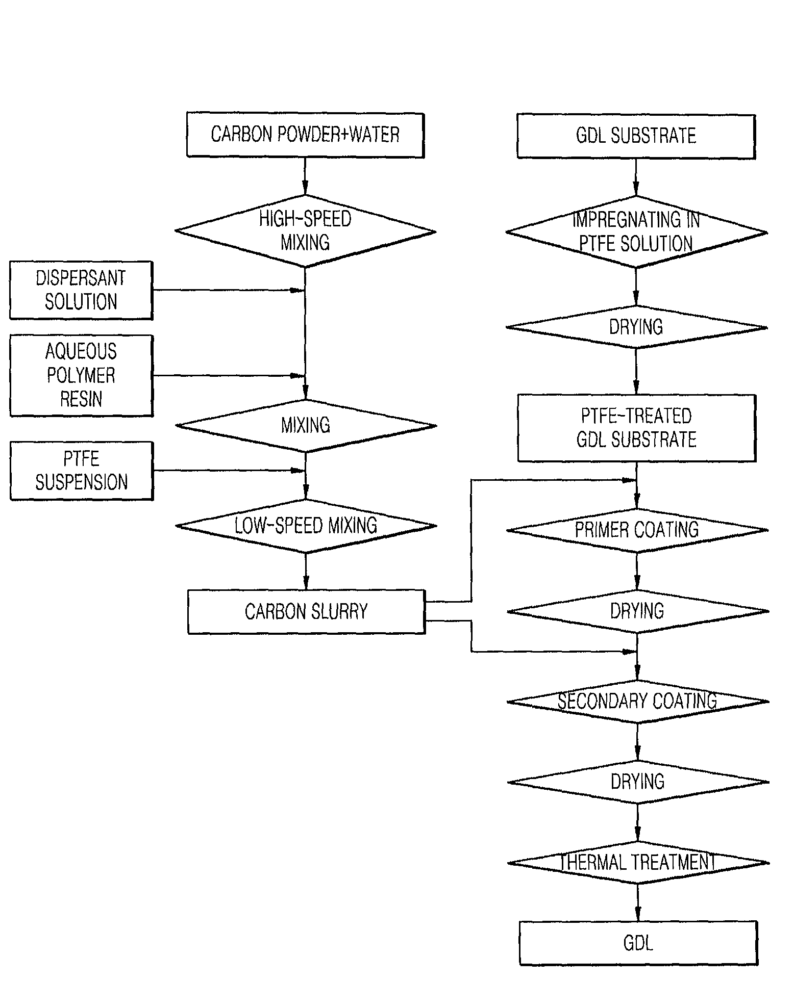
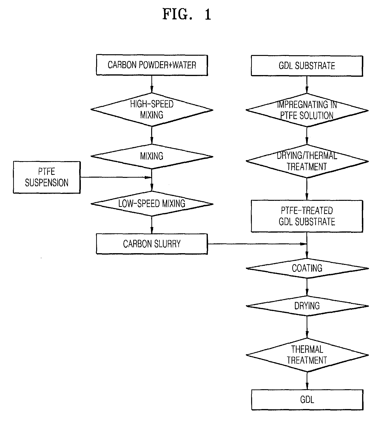
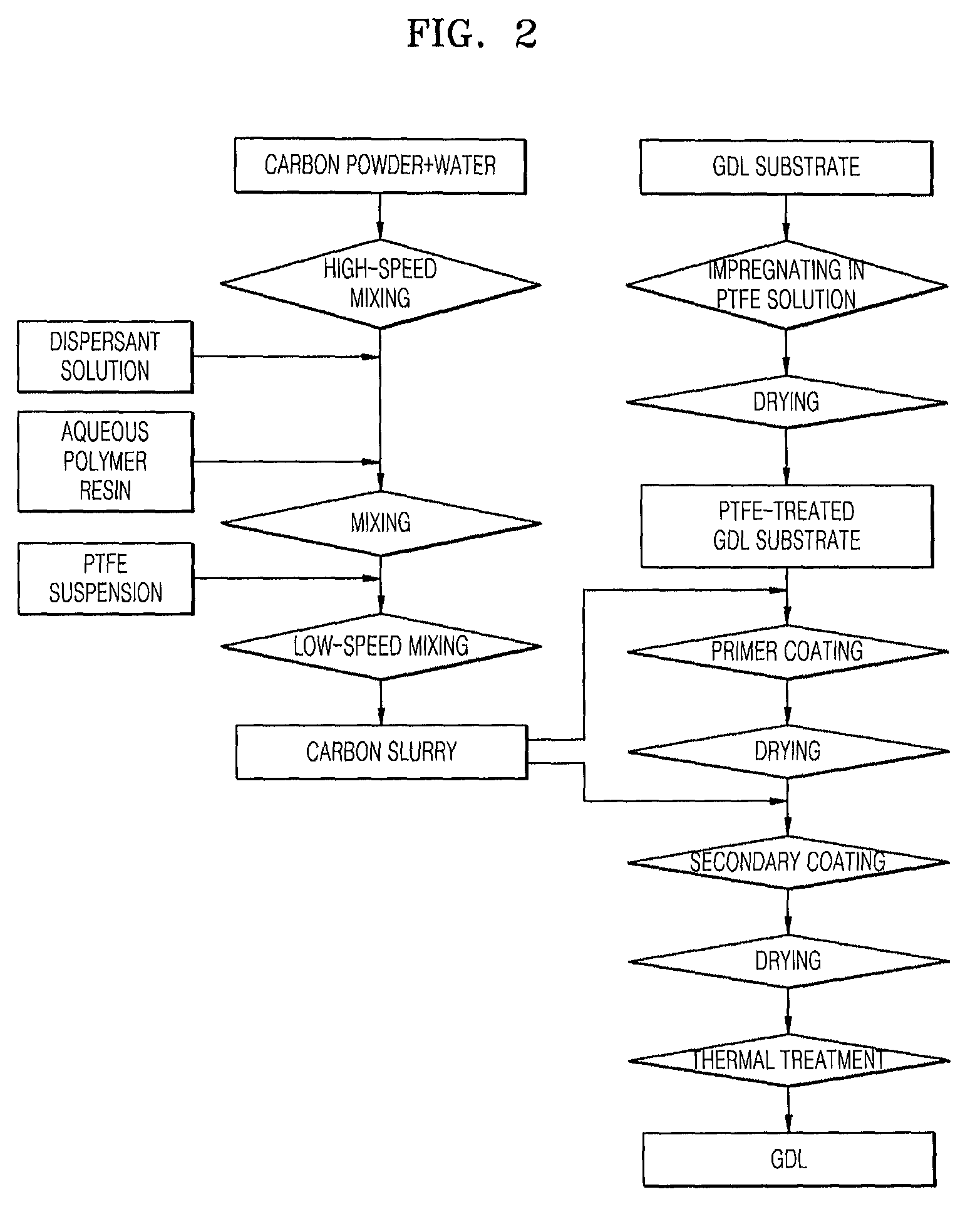
[0073]1,000 g of ultra pure water was added to Vulcan XC-72 (Cabot) and the components were blended in a high-speed mixer (2,000 rpm). A dispersant, Triton X-100 was added thereto and the components were dispersed for one hour. 30 g of carboxymethylcellulose was added to the dispersed solution, and the components were further dispersed for one hour. 30 wt % of PTFE (30J, Dupont) was added to the dispersed solution, and the components were stirred in a low-speed mixer (200 rpm) for one hour to make carbon slurries. At this time, the content of PTFE was adjusted to 30 parts by weight based on 100 parts by weight of the carbon powder.

[0074]Carbon substrates (TGPH-060, Toray) were immersed in a PTFE suspension for five minutes and dried in a 80° C. dry oven for one hour so that the content of PTFE was 30 wt %. Then, the carbon slurries were coated on the carbon substrates using a knife coating method and dried in a 80° C. dry oven for one hour to obtain primer layers with a thickness of...

example 2

[0080]Gas diffusion layers and fuel cells including the same were manufactured in the same manner as in Example 1 except that carbon cloths (AvCarb™ 1071 HCB or AvCarb™ 1071 CCB, Ballard Material Products) were used as substrates of the gas diffusion layers. A voltage drop with respect to current density of the fuel cells was measured.


PUM


Abstract

A common method of preparing a gas diffusion layer for a fuel cell has problems in that a microporous layer is impregnated into a substrate, thereby lowering the porosity of the substrate, and cracks are created on a surface of a gas diffusion layer prepared using the method. Provided is a method of reproducibly preparing a gas diffusion layer with a uniform thickness and no cracks based on the principle of a primer coating method, wherein a first microporous layer is hardly impregnated into a substrate and uniformly covers a surface of the substrate, and at least one microporous layer is further coated on the first microporous layer. Provided is also a fuel cell showing improved performance by enhancing utilization of a catalyst layer and guaranteeing a uniform diffusion of fuel and an efficient discharge of a product.

Description

TECHNICAL FIELD[0001]The present invention relates to a method of preparing a gas diffusion layer for a fuel cell, and more particularly, to a method of preparing a gas diffusion layer for a fuel cell, which has a uniform thickness, no cracks, and good reproducibility.BACKGROUND ART[0002]Polymer electrolyte membrane fuel cells (PEMFCs) can be classified into fuel cells using hydrogen or a hydrocarbon gas and direct methanol fuel cells (DMFCs) using an aqueous methanol solution according to the type of fuel which is supplied to a fuel electrode. As compared with other fuel cells, PEMFCs have features such as a low operating temperature, high efficiency, high current density and energy density, short starting time, and a rapid response speed in response to a load change. When comparing PEMFCs with secondary batteries that have been developed as power sources of electric vehicles, PEMFCs have an energy density of about 200 to several thousands Wh / kg, while secondary batteries have an e...

Claims


Application Information

Patent Timeline
IPC IPC(8): H01M4/96H01M4/04
CPCH01M4/8807H01M4/8821H01M8/0234Y02E60/523H01M8/1002H01M8/1011H01M2008/1095H01M8/0245H01M8/1007Y02E60/50A47G25/483
Inventor LEE, EUN-SOOKYANG, KYOUNG-HUNJUNG, HEE-ROKKIM, TAE-HEEHAN, SUN-KYUNGLEE, JEONG-KYOUSEO, YUN-HEEPARK, JONG-HO
Owner LEE EUN SOOK
Why Eureka
Try Eureka