Apparatus and method for applying coatings onto the interior surfaces of components and related structures produced therefrom

a technology of interior surfaces and coatings, applied in the direction of solid-state diffusion coatings, electric/magnetic/electromagnetic heating, magnetic bodies, etc., can solve the problems of limited use life of small and medium-sized (20 to 40 mm) gun barrels, toxic materials, and difficult disposal of materials, so as to control the effect of effectiveness

Active Publication Date: 2009-01-15
UNIV OF VIRGINIA ALUMNI PATENTS FOUND
View PDF1 Cites 68 Cited by
  • Summary
  • Abstract
  • Description
  • Claims
  • Application Information

AI Technical Summary

Benefits of technology

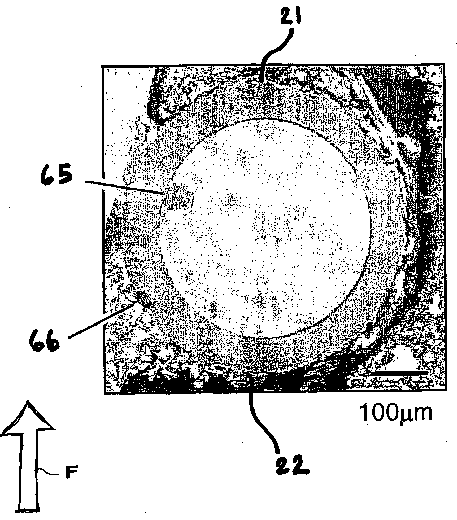
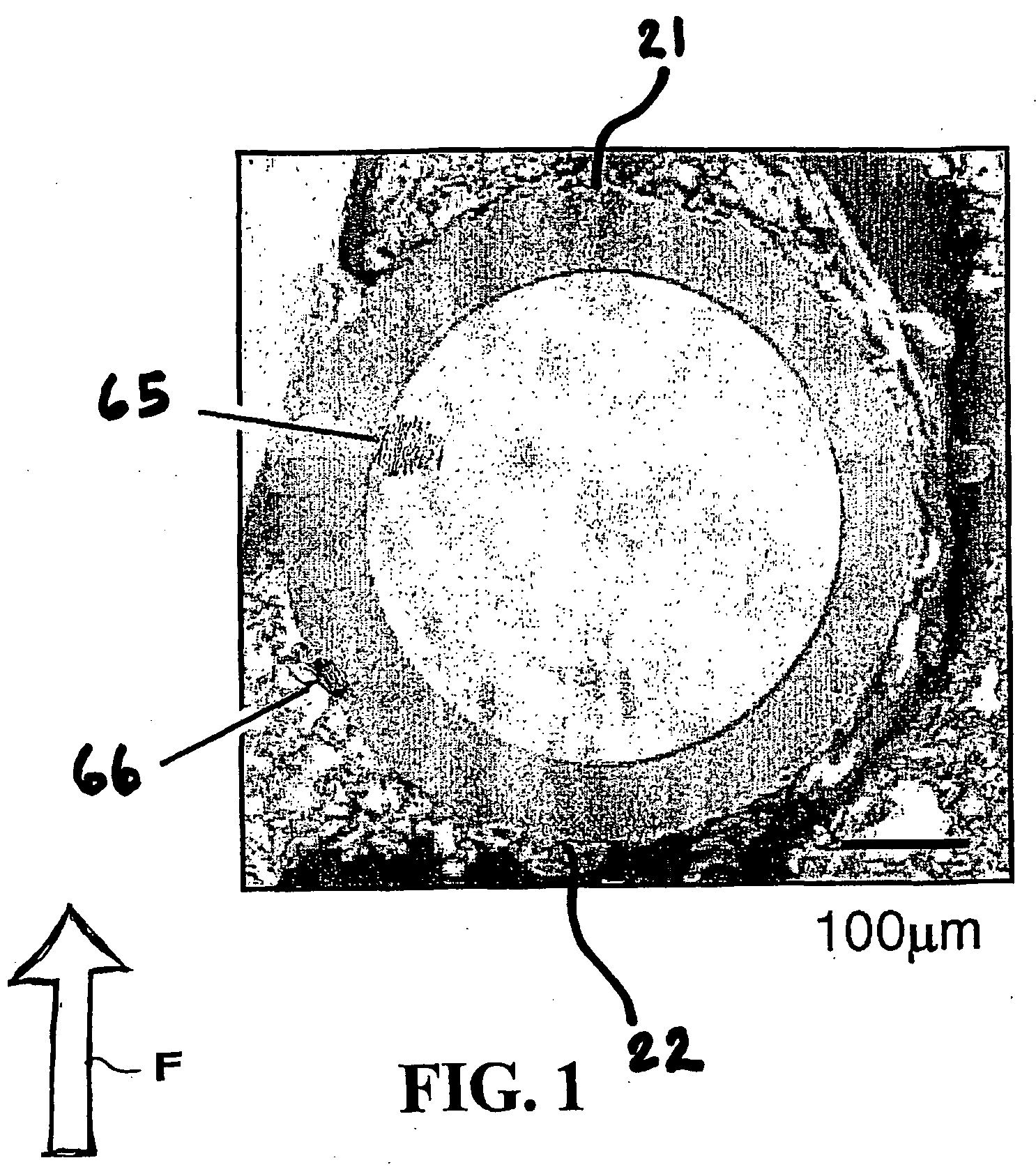
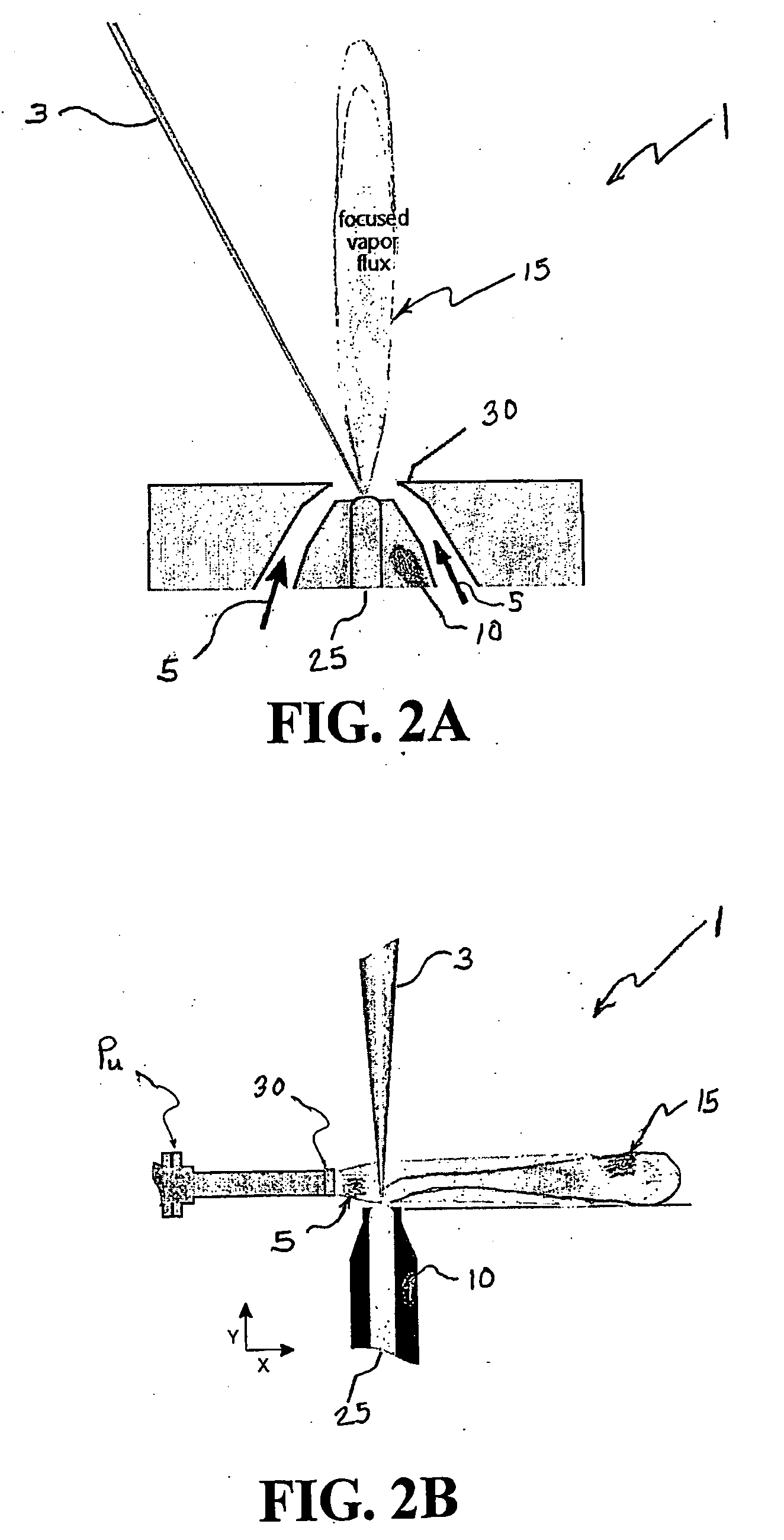
[0009]An aspect of an embodiment of the present invention provides a methodology and system for applying coatings onto the interior surfaces of components. The approach comprises a vapor creation device (for example an electron beam or laser that evaporates a single or multiplicity of solid or liquid sources), a vacuum chamber having a moderate gas pressure (between about 10−4 to about 103 Torr) and a inert gas jet having controlled velocity and flow fields of gas jet. The gas jet is created by a rarefied, inert gas supersonic expansion through a nozzle. By controlling the carrier gas flow into a region upstream of the nozzle an upstream pressure is achieved (i.e. the gas pressure prior to its entrance into the processing chamber through the nozzle). The carrier gas flow and chamber pumping rate control the downstream (or chamber) pressure (downstream of the nozzle). The ratio of the upstream to downstream pressure along with the size and shape of the nozzle opening controls the speed of the gas entering the chamber. The carrier gas molecular weight (compared to that of the vapor) and the carrier gas speed controls its effectiveness in redirecting the vapor atoms via binary collisions towards the substrate. The speed and flux of the atoms entering the chamber, the nozzle parameters, and the operating chamber pressure can all be varied leading to a wide range of accessible processing conditions. Vapor created from a source is transported into the interior regions of a component using binary collisions between the vapor and gas jet atoms. Under certain process conditions these collisions enable the vapor atoms to scatter onto the interior surfaces of the component and deposit.

Problems solved by technology

The useful lifetime of small and medium diameter (20 to 40 mm) gun barrels is limited by damage of the interior surfaces resulting from mechanical and thermochemical effects related to passing a projectile through the gun bore and subsequent exposure of the interior surface to hot propellant gases.
These coatings provide adequate performance; unfortunately hexalavent chrome is created during the electrodeposition process.
This material is toxic and difficult to dispose of.
The internal surfaces, however, are hidden or limited from sight making the coating of internal surfaces with very uniform thickness distribution and a high quality microstructure very difficult or impossible.
While high pressure CVD using metal-organic precursors may at first provide a promising approach, non-uniform deposition, vapor toxicity issues and low deposition rates plague this approach.
Thus, the desired combination of non-line-of-sight coating capability, limited-line-of sight capability, high deposition uniformity, environmental inertness and compositional flexibility required has been difficult to achieve.
In most PVD based processing approaches, however, it is not possible to uniformly coat the interior of hollow tubular substrates without spatially distributed sources (such as cylindrical magnetron sputtering (CMS) where source targets are inserted into the interior of the part).
This arises because the vapor atoms are created in a high vacuum that results in nearly collisionless vapor transport to the substrate.
In addition, the ability of these processes to deposit coatings into the grooves found in rifled gun barrels is also an issue.
Its application to smaller diameters, however, is not feasible because of issues related to the stability of the ionization and deposition processes involved.

Method used


Image

  • Apparatus and method for applying coatings onto the interior surfaces of components and related structures produced therefrom
  • Apparatus and method for applying coatings onto the interior surfaces of components and related structures produced therefrom
  • Apparatus and method for applying coatings onto the interior surfaces of components and related structures produced therefrom

Examples


Embodiment Construction

[0051]In general, physical vapor deposition processes can be considered as multi-step processes; a) vapor creation, b) vapor transport, c) vapor adatom adsorption and d) assembly on the substrate (component). Methodologies for the creation of the vapor are many and have been widely researched as has the assembly processes at the substrate. There is, however, a need for, among other things, an improved control of the vapor transport processes that enable increased process efficiency, improved composition control, limited-line-of-sight (LLOS) and non-line-of-sight (NLOS) deposition. Such attributes would promise to greatly improve the economy of PVD processes and other process types and its potential range of applications.

[0052]One approach of an aspect of an embodiment of the present invention is to alter the vapor transport step through the use of binary collisions between vapor atoms and a moving background gas. This is enabled by the use of certain chamber pressures to control the...


PUM

PropertyMeasurementUnit
pressureaaaaaaaaaa
pressureaaaaaaaaaa
diameteraaaaaaaaaa

Abstract

Provided is a methodology and system for applying coatings onto the interior surfaces of components. The approach comprises a vapor creation device (for example an electron beam or laser that evaporates a single or multiplicity of solid or liquid sources), a vacuum chamber having a moderate gas pressure (between about 10−4 to about 103 Torr) and a inert gas jet having controlled velocity and flow fields of gas jet. The gas jet is created by a rarefied, inert gas supersonic expansion through a nozzle. By controlling the carrier gas flow into a region upstream of the nozzle an upstream pressure is achieved (i.e. the gas pressure prior to its entrance into the processing chamber through the nozzle). The carrier gas flow and chamber pumping rate control the downstream (or chamber) pressure (i.e., downstream of the nozzle). The ratio of the upstream to downstream pressure along with the size and shape of the nozzle opening controls the speed of the gas entering the chamber. The carrier gas molecular weight (compared to that of the vapor) and the carrier gas speed controls its effectiveness in redirecting the vapor atoms via binary collisions towards the substrate. The speed and flux of the atoms entering the chamber, the nozzle parameters, and the operating chamber pressure can all vary leading to a wide range of accessible processing conditions. Vapor created from a source is transported into the interior regions of a component using binary collisions between the vapor and gas jet atoms. Under certain process conditions these collisions enable the vapor atoms to scatter onto the interior surfaces of the component and deposit.

Description

CROSS-REFERENCES TO RELATED APPLICATIONS[0001]The Present invention claims priority from U.S. Provisional Patent Application Ser. No. 60 / 535,442, filed Jan. 8, 2004, entitled “Method and System for Applying Coatings onto the Interior Surfaces of Components,” and Application Ser. No. 60 / 637,522, filed Dec. 20, 2004, entitled “Method and System for Applying Coatings onto the Interior Surfaces of Components and Resultant Structure there from,” the entire disclosures of which are hereby incorporated by reference herein in their entirety.US GOVERNMENT RIGHTS[0002]This invention was made with United States Government support under Grant No. FA8201-04-P-2018, awarded by the United States Air Force. The United States Government has certain rights in the invention.FIELD OF THE INVENTION[0003]The present invention provides a method and an apparatus for efficiently applying a coating to a component by creating an atomic vapor flux, and more particularly coating the interior of a component or a...

Claims


Application Information

Patent Timeline
Patent Type & Authority Applications(United States)
IPC IPC(8): C23C14/28B05B13/00C23C14/30C23C14/34C23C14/35C23C4/00C23C16/00B05D1/08C23C14/38C23C14/32B05D7/22C23C14/04F41A21/02F41A21/04F41A21/20F41A21/22
CPCC23C14/042C23C14/046C23C14/228F41A21/22F41A21/04F41A21/20F41A21/02
Inventor HASS, DEREK D.WADLEY, HAYDN N. G.
Owner UNIV OF VIRGINIA ALUMNI PATENTS FOUND
Why Eureka
Try Eureka