Automotive supercharging apparatus

a supercharging apparatus and motor technology, applied in mechanical equipment, machines/engines, magnetic circuit shapes/forms/construction, etc., can solve the problems of insufficient supercharging capacity of centrifugal supercharging apparatus, limit to how much gear ratio can be increased, and insufficient supercharging capacity of low-speed regions, etc., to reduce costs, suppress the effect of inverter and battery capacity increase and boost pressur

Active Publication Date: 2009-01-22
MITSUBISHI ELECTRIC CORP
View PDF6 Cites 58 Cited by
  • Summary
  • Abstract
  • Description
  • Claims
  • Application Information

AI Technical Summary

Benefits of technology

[0017]Thus, the one-way clutch pulley is in a disengaged state in a low-speed region in which the load torque on the compressor is comparatively small, and the compressor is driven by the driving torque from the electric motor-generator. In a high-speed region in which the load torque on the compressor increases, because the driving torque from the electric motor-generator is insufficient on its own to drive the compressor, the one-way clutch pulley moves to the engaged state and the compressor is driven by the driving torque from the engine. Using a configuration of this kind, driving of the compressor by the electric motor-generator is limited to the low-speed region, suppressing increases in inverter and battery capacity, enabling costs to be reduced. Furthermore, because the compressor can be driven by the engine if the inverter fails, the vehicle can continue to operate.
[0018]When engine speed is less than or equal to the predetermined value, the electric motor-generator is driven as an electric motor, and the compressor is driven by the electric motor-generator. The predetermined value is an engine speed that can achieve a rotational speed of the turbine shaft at which operation of the compressor becomes effective as a supercharger, a rotational speed in the order of 4.5×10⁴ rpm, for example. Thus, the rotational speed of the turbine shaft is increased to a rotational speed at which the compressor operates effectively as a supercharger, ensuring boost pressure. Consequently, boost pressure can be ensured even in the low-speed region during idling reduction and idling.

Problems solved by technology

Centrifugal automotive supercharging apparatuses are more efficient than positive displacement ones, and are more lightweight, but one problem is that supercharging capacity is insufficient in low-speed regions.
However, there is a limit to how much the gear ratio can be increased in the configuration of the epicyclic gear sets according to Patent Literature 1, and supercharging capacity of the centrifugal supercharging apparatus is insufficient in a micro-low velocity rotational frequency range from idling to approximately 1,500 rpm.
Activation during engine shutdown is also fundamentally impossible, preventing sufficient boost pressure from being achieved immediately after restarts from idling reduction, etc.
In diesel engine vehicles in particular, when turbo lag arises, the amount of air is insufficient, increasing particulate matter (PM).
In the technique according to Patent Literature 2, since it is necessary to introduce an additional motor that controls the rotational speed of the compressor, and the planetary gears, the sun gear, and the ring gear are coupled to three shafts, i.e., to the motor, to the engine, and to the compressor, one disadvantage has been that the construction of the planetary gear mechanism is complex and a high degree of control is required, increasing cost.
There have also been other problems such as rotational speed control of the compressor no longer being possible if the motor fails, making continuation of operation practically impossible.
In the technique according to Patent Literature 3, because the supercharger is driven by an electric motor, one problem has been that continuation of operation becomes practically impossible if the electric motor fails.
Because the supercharger is driven in a high-speed rotation region, there have also been other problems such as the electric power that is demanded of the electric motor exceeding 1 kW, requiring a high-capacity inverter and battery in low-voltage systems in the vehicle, such as the 12 V system, etc., making significant cost increases unavoidable.

Method used


Image

  • Automotive supercharging apparatus
  • Automotive supercharging apparatus
  • Automotive supercharging apparatus

Examples


embodiment 1

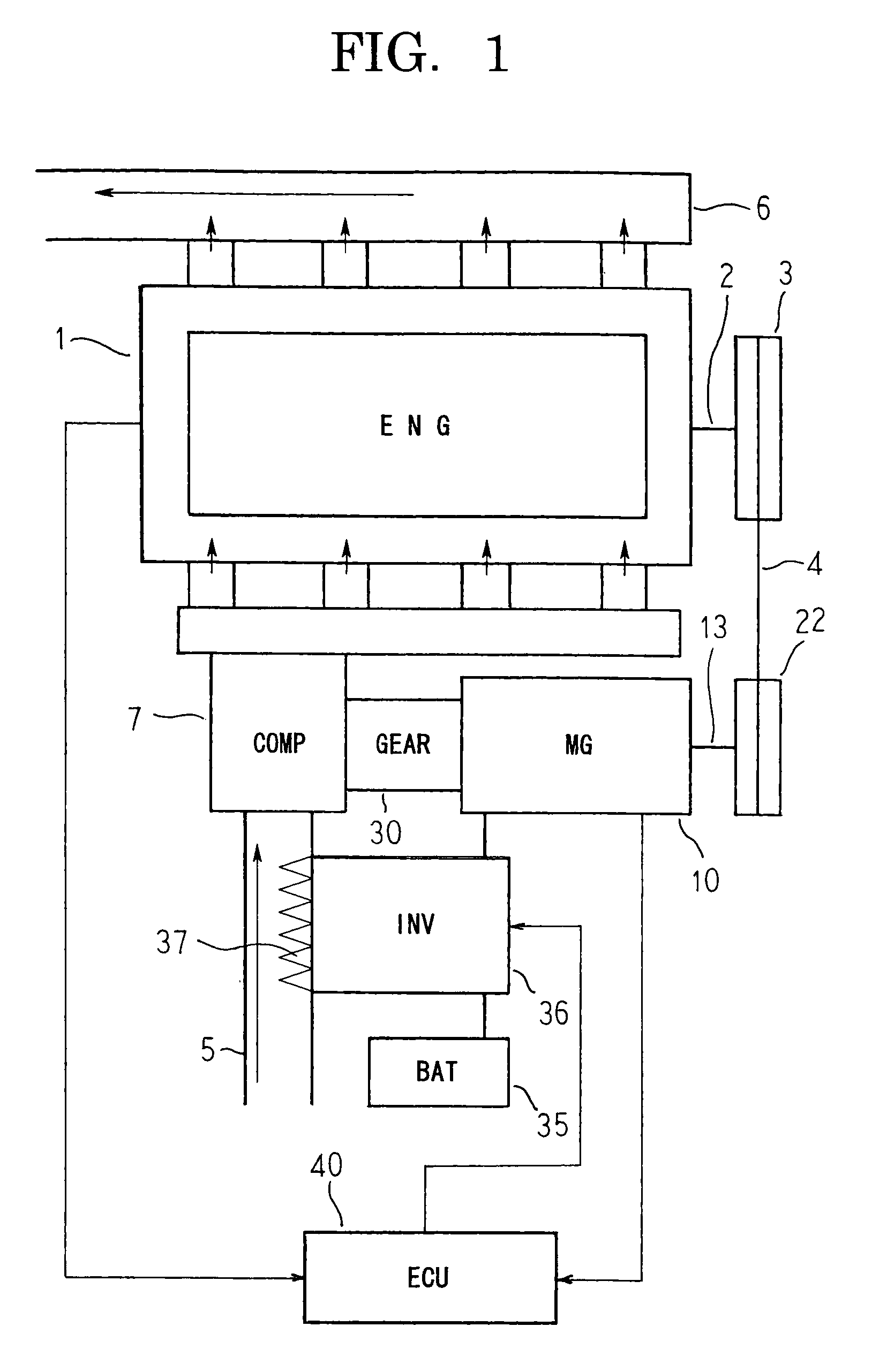
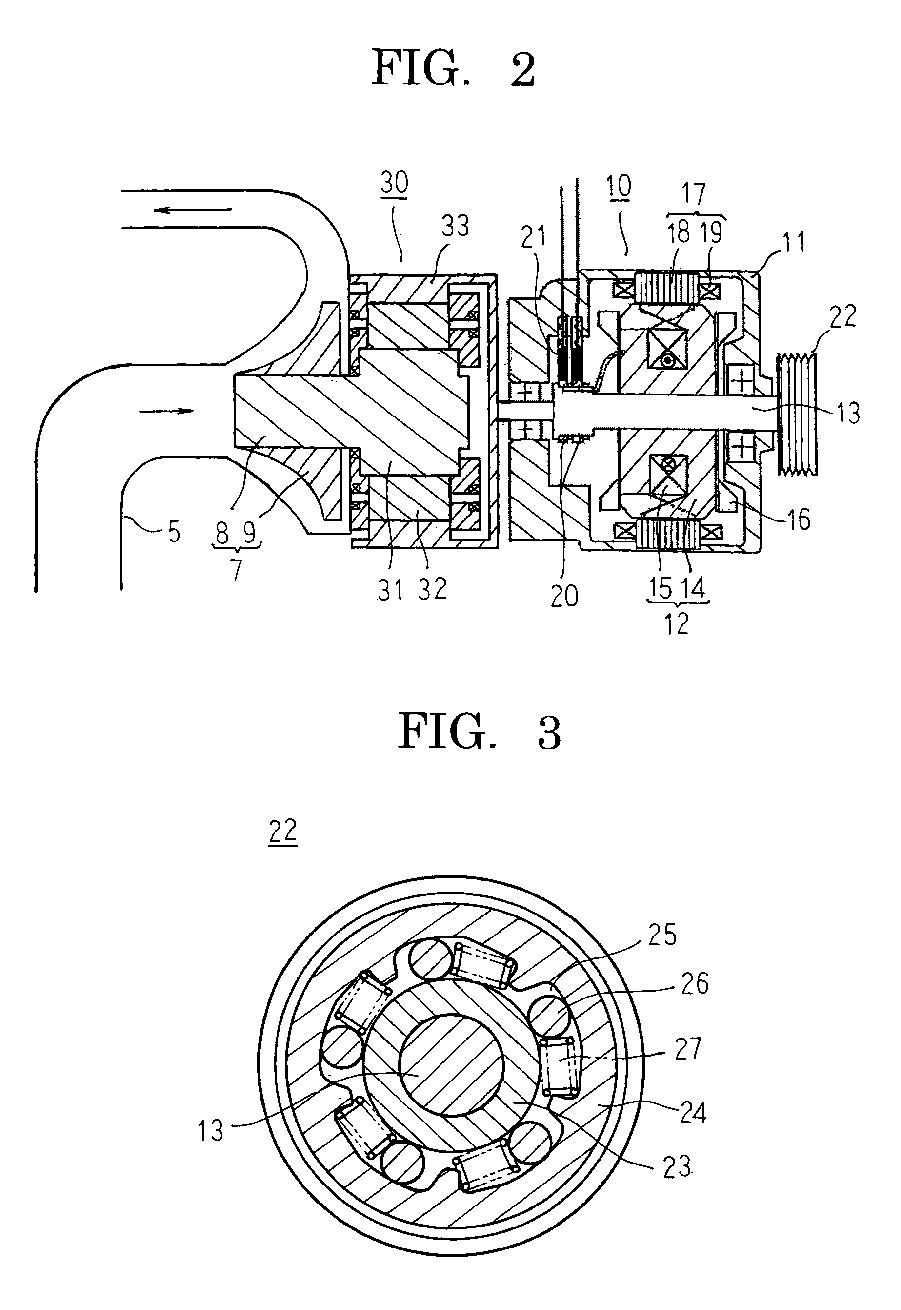
[0026]FIG. 1 is a system configuration diagram that shows an automotive supercharging apparatus according to Embodiment 1 of the present invention, FIG. 2 is a cross section that schematically shows a power transmission pathway in the automotive supercharging apparatus according to Embodiment 1 of the present invention, and FIG. 3 is a cross section that shows a one-way clutch pulley that can be used in the automotive supercharging apparatus according to Embodiment 1 of the present invention.

[0027]In FIG. 1, air is supplied to an engine 1 by means of intake piping 5, and exhaust gas is discharged after combustion by means of exhaust piping 6. A crank pulley 3 is fixed to a crank shaft 2 that constitutes an output shaft of the engine 1.

[0028]An automotive supercharging apparatus includes: a compressor 7 that is disposed in the intake piping 5, and that compresses air that is supplied to the engine 1; an electric motor-generator 10 that includes an electric motor function and a genera...

embodiment 2

[0076]FIG. 4 is a system configuration diagram that shows an automotive supercharging apparatus according to Embodiment 2 of the present invention.

[0077]In FIG. 4, a first pulley 41 is fixed to a rotating shaft 13 alongside a one-way clutch pulley 22. An oil pump 42 includes a second pulley 44 that is fixed to a rotating shaft 43, and supplies oil to lubricate an epicyclic gear apparatus 30. A second belt 45 is looped around the first and second pulleys 41 and 44 so as to transmit driving torque from an electric motor-generator 10 to the oil pump 42.

[0078]Moreover, the rest of this embodiment is configured in a similar manner to Embodiment 1 above.

[0079]According to Embodiment 2, the oil pump 42 can be driven when the engine 1 is stopped by operating the electric motor-generator 10 as an electric motor. Thus, oil is constantly supplied to the epicyclic gear apparatus 30 from the oil pump 42 while the compressor 7 is driven at high speed by the electric motor-generator 10, enabling t...

embodiment 3

[0080]FIG. 5 is a system configuration diagram that shows an automotive supercharging apparatus according to Embodiment 3 of the present invention, and FIG. 6 is a cross section that schematically shows a power transmission pathway in the automotive supercharging apparatus according to Embodiment 3 of the present invention.

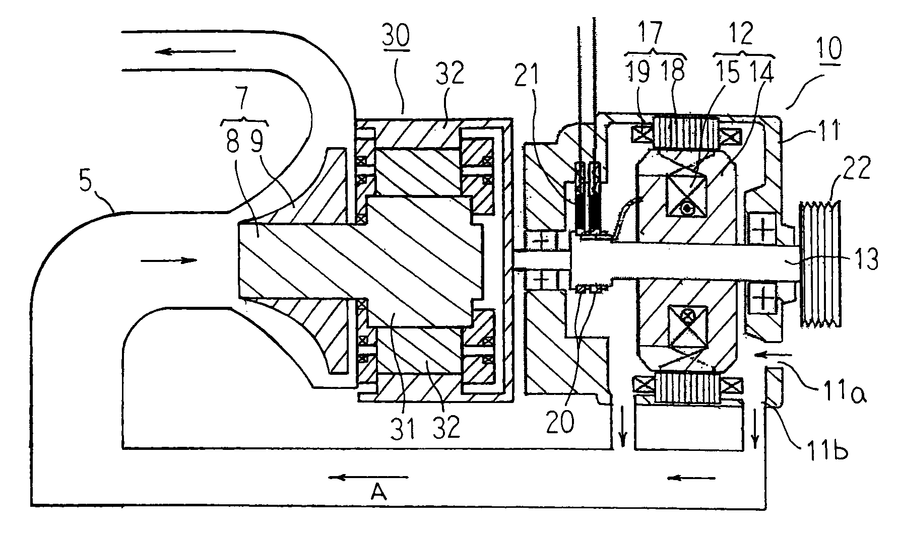
[0081]In FIGS. 5 and 6, an air intake aperture 11a and an air discharge aperture 11b are disposed on a housing 11 of an electric motor-generator 10, and intake piping 5 upstream from a compressor 7 is linked to the air discharge aperture 11b. Thus, an intake airflow A is formed in which air is sucked in through the air intake aperture 11a into the housing 11 by driving the compressor 7, cools a rotor 12 and a stator 17, is then discharged through the air discharge aperture 11b of the housing 11, flows through the intake piping 5, and is supplied to the compressor 7.

[0082]Moreover, the rest of this embodiment is configured in a similar manner to Embodiment 1 above....


PUM


Abstract

An electric motor-generator and an engine are linked using a first belt that is looped around a crank pulley that is mounted to a crank shaft and a one-way clutch pulley that is mounted to a rotating shaft. An electronic control unit drives the electric motor-generator as an electric motor and drives the compressor by the electric motor-generator if engine speed is less than or equal to a predetermined value.

Description

BACKGROUND OF THE INVENTION[0001]1. Field of the Invention[0002]The present invention relates to an automotive supercharging apparatus, and particularly relates to an automotive supercharging apparatus to which a centrifugal compressor is mounted that can be driven by both an engine shaft and an electric motor-generator shaft.[0003]2. Description of the Related Art[0004]Automotive supercharging apparatuses that function as superchargers that receive torque from a belt and a pulley that are connected to an engine pressurize air that is used by the engine to enable the engine to burn a larger quantity of fuel, thereby increasing output and torque. There are two basic types of these automotive supercharging apparatuses: positive displacement; and centrifugal. Centrifugal automotive supercharging apparatuses are more efficient than positive displacement ones, and are more lightweight, but one problem is that supercharging capacity is insufficient in low-speed regions.[0005]Thus, multist...

Claims


Application Information

Patent Timeline
Patent Type & Authority Applications(United States)
IPC IPC(8): F02B33/44
CPCF02B33/40F02B39/12F02B39/10F02B39/04
Inventor INOUE, MASAYAASAO, YOSHIHITO
Owner MITSUBISHI ELECTRIC CORP
Why Eureka
Try Eureka