Dye-sensitized solar cell

a solar cell and dye-sensitized technology, applied in the field of solar cells, can solve the problems of dye-sensitized solar cells, which have gradually become hot research problems, and are limited to some special applications, and achieve the effect of improving the efficiency of elements and improving the injection efficiency of electrons

Inactive Publication Date: 2009-01-22
NATIONAL YUNLIN UNIVERSITY OF SCIENCE AND TECHNOLOGY
View PDF2 Cites 14 Cited by
  • Summary
  • Abstract
  • Description
  • Claims
  • Application Information

AI Technical Summary

Benefits of technology

[0007]In view of the above problems, the present invention is directed to a dye-sensitized solar cell, capable of improving the injection efficiency of electrons, so as to significantly improve the efficiency of the elements.
[0008]The present invention provides a dye-sensitized solar cell, which includes a photosensitive dye layer, a first electrode layer, a second electrode layer, an energy-level intermediary layer, a first substrate, and a second substrate. The photosensitive dye layer is used to receive the sunlight and transfer the sunlight to electrons and holes for being released. The first electrode layer is disposed on one side of the photosensitive dye layer to receive electrons generated from the photosensitive dye layer. The second electrode layer is disposed on the other side of the photosensitive dye layer opposite to the first electrode layer to receive the holes generated from the photosensitive dye layer. The energy-level intermediary layer is disposed between the first electrode layer and the photosensitive dye layer to improve the efficiency for transporting and injecting the electrons into the first electrode layer from the photosensitive dye layer. The first substrate is disposed on the other side of the first electrode layer opposite to the energy-level intermediary layer, and the second substrate is disposed on the other side of the second electrode layer opposite to the photosensitive dye layer.
[0014]According to the dye-sensitized solar cell of the present invention, an energy-level intermediary layer is disposed between the first electrode layer and the photosensitive dye layer to improve the efficiency for transporting and injecting the electrons into the first electrode layer from the photosensitive dye layer. Particularly, when the photosensitive dye is excited by the sunlight, the electrons are transited to an excited state, and at this time, the electrons are effectively injected into the electron transport layer or the first electrode layer through the energy-level intermediary layer under the tunneling effect. The energy-level intermediary layer is of metal oxide or metal fluoride, which is evaporated on the surface of the electron transport layer, so as to enlarge the surface area of the electron transport layer, and thus improving the electron injection flux. The existence of the energy-level intermediary layer offers the chance to prevent the electrons already injected into the electron transport layer from coming back into the dye layer, and thus inhibiting the generation of the counter current. In this way, the injection efficiency of electrons can be effectively improved, and thus, the efficiency of the elements is also improved.

Problems solved by technology

Although the silicon solar cells have relatively high photoelectric conversion efficiency, as the manufacturing process is complicated and the cost is high, it is limited to some special applications.
Accordingly, the dye-sensitized solar cell has gradually become a hot research issue in this field.
When the photosensitive dye absorbs the sunlight, the photosensitive dye is excited by the light, and the electrons are transited to an excited state, but the excited state is not stable, the electrons are soon transferred to the semiconductor electrode.

Method used


Image

  • Dye-sensitized solar cell
  • Dye-sensitized solar cell
  • Dye-sensitized solar cell

Examples


Embodiment Construction

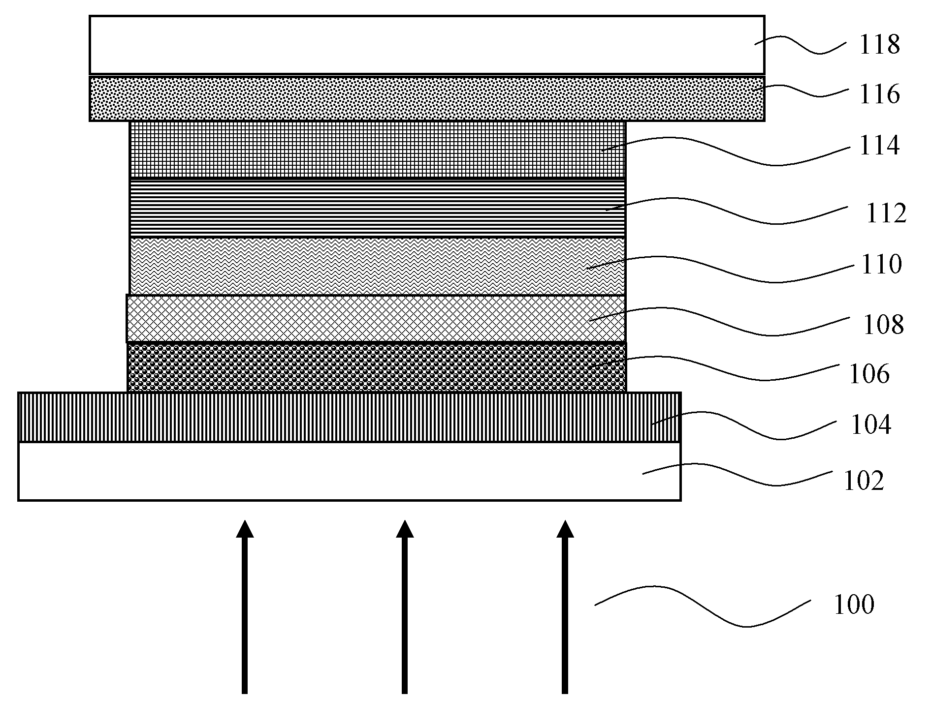
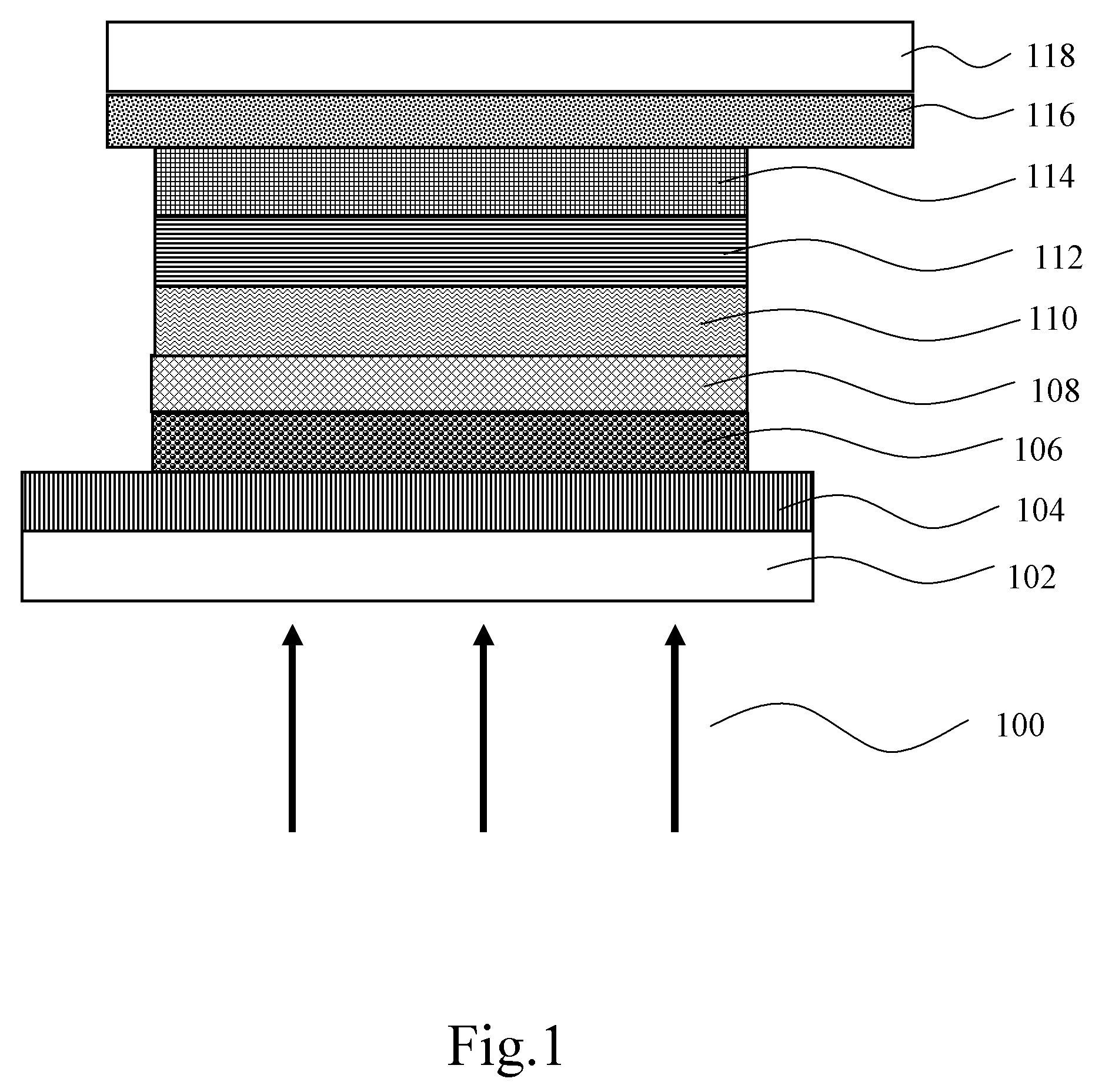
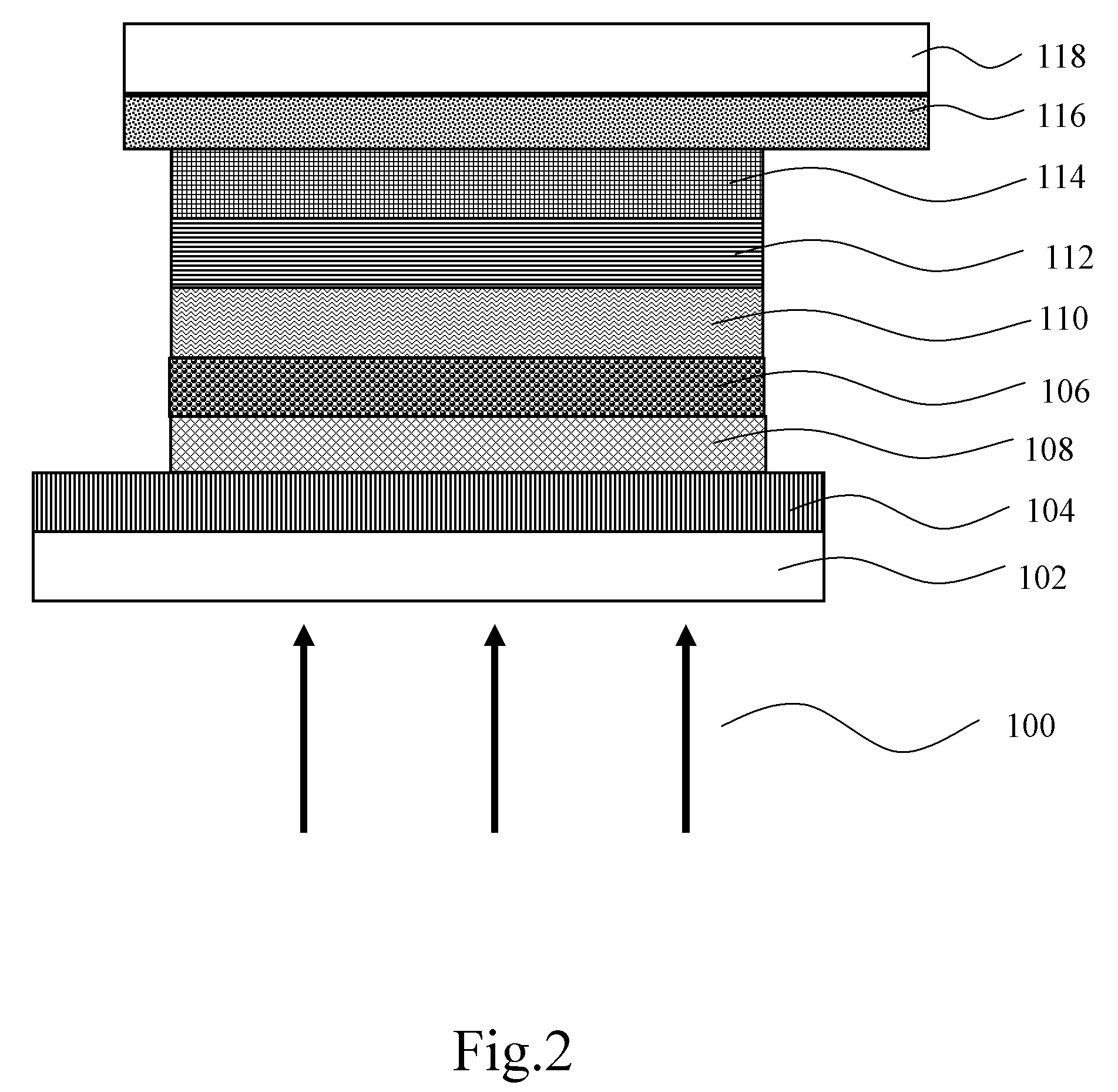
[0021]Referring to FIG. 1, it is a schematic cross-sectional view of a structure of a dye-sensitized solar cell according to the present invention. As shown in FIG. 1, the dye-sensitized solar cell sequentially includes a first substrate 102, a first electrode layer 104, an electron transport layer 106, an energy-level intermediary layer 108, a photosensitive dye layer 110, an electrolyte 112, a second electrode layer 114, a transparent electrode 116, and a second substrate 118.

[0022]In an embodiment of the present invention, the first electrode layer 104 is a transparent conductive glass, and the material of the transparent conductive glass is a glass with a conductive film of fluorine-doped tin dioxide (SnO2: F) or indium-tin oxide (ITO) plated thereon.

[0023]In this embodiment, the electron transport layer 106 is disposed between the first electrode layer 104 and the energy-level intermediary layer 108, and the electron transport layer 106 is made of titanium dioxide (TiO2). Alter...


PUM


Abstract

A dye-sensitized solar cell includes a first electrode layer, a photosensitive dye layer, a second electrode layer, an energy-level intermediary layer, a first substrate and a second substrate. The photosensitive dye layer is used to receive sunlight and convert the sunlight to electrons and holes for being released. The first electrode layer is disposed on one side of the photosensitive dye layer to receive the electrons generated from the photosensitive dye layer. The second electrode layer is disposed on the other side of the photosensitive dye layer to receive the holes generated from the photosensitive dye layer. The energy-level intermediary layer is positioned between the first electrode layer and the photosensitive dye layer, so as to improve an injection efficiency of electrons and to prevent the generation of counter current, and thereby enhancing photoelectric conversion efficiency of the cell.

Description

BACKGROUND OF THE INVENTION[0001]1. Field of the Invention[0002]The present invention relates to a solar cell. More particularly, the present invention relates to a dye-sensitized solar cell.[0003]2. Related Art[0004]Due to the problems of global climate change, air pollution, and resource shortage, the possibility of taking solar cells as one of the main sources for power supply has widely drawn more and more attentions, which is exactly the reason for the rapid development of the market of silicon-based solar cells in recent years. The principle of the silicon-based solar cells is based on the photovoltaic effect of the semiconductor. Although the silicon solar cells have relatively high photoelectric conversion efficiency, as the manufacturing process is complicated and the cost is high, it is limited to some special applications. Therefore, many main research institutes all over the world are dedicated to the research of technologies relevant to solar energy, and expect to devel...

Claims


Application Information

Patent Timeline
Patent Type & Authority Applications(United States)
IPC IPC(8): H01L31/00
CPCH01G9/2031H01G9/2036Y02E10/542H01L51/0086H01G9/2059H10K85/344
Inventor LEE, RONG-HOHUANG, YU-WEI
Owner NATIONAL YUNLIN UNIVERSITY OF SCIENCE AND TECHNOLOGY
Why Eureka
Try Eureka