Mass spectrometer

Active Publication Date: 2009-01-22
HITACHI HIGH-TECH CORP
View PDF20 Cites 7 Cited by
  • Summary
  • Abstract
  • Description
  • Claims
  • Application Information

AI Technical Summary

Benefits of technology

[0008]Ions are ejected like pulses from an ion trap in a very short time, so that a time-of-flight mass spectrometer cannot measure those ions efficiently. In order to solve such a problem, JP-A-2005-044594 describes a method that uses a collisional-damping chamber to lengthen the time distribution of ions that have been ejected massively from an ion trap in a short time; thereby, it is enabled to send those ions continuously into a time-of-flight mass spectrometer. As a result, ions come to be measured very efficiently. According to the technique described in JP-A-2005-044594, however, it is still insufficie

Problems solved by technology

Ions are ejected like pulses from an ion trap in a very short time, so that a time-of-flight mass spectrometer cannot measure those ions efficiently.
According to the technique described in JP-A-2005-044594, however, it is still insufficient to improve the utilization efficiency of ions.
Thus it is not so easy to control the ejection time of ions properly.
This has been a problem conventionally.
This has also been a problem conventionally.
Furthermore, the ejection time of ions might also change if the DC potential on the center axis of th

Method used


Image

  • Mass spectrometer
  • Mass spectrometer
  • Mass spectrometer

Examples


first embodiment

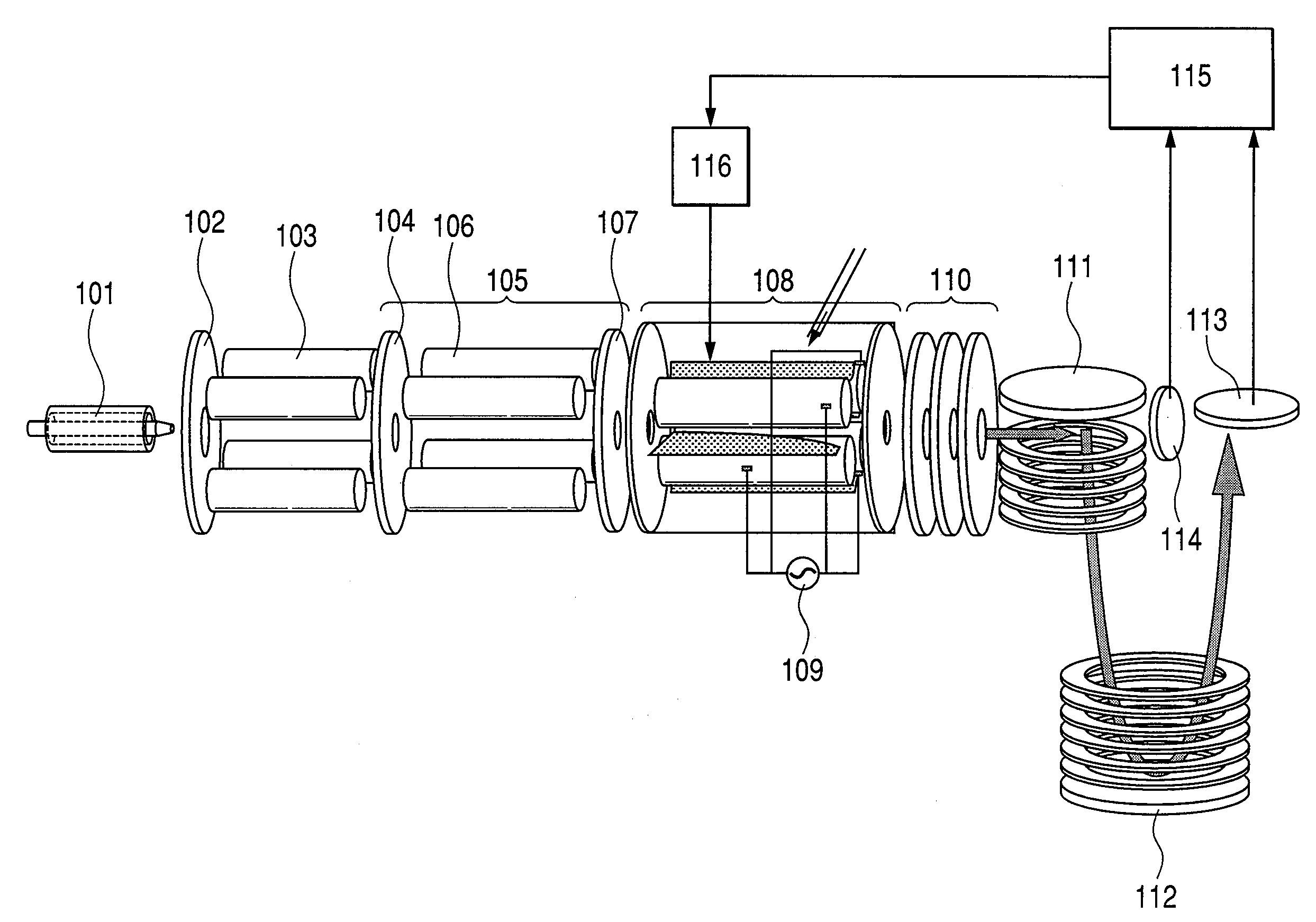
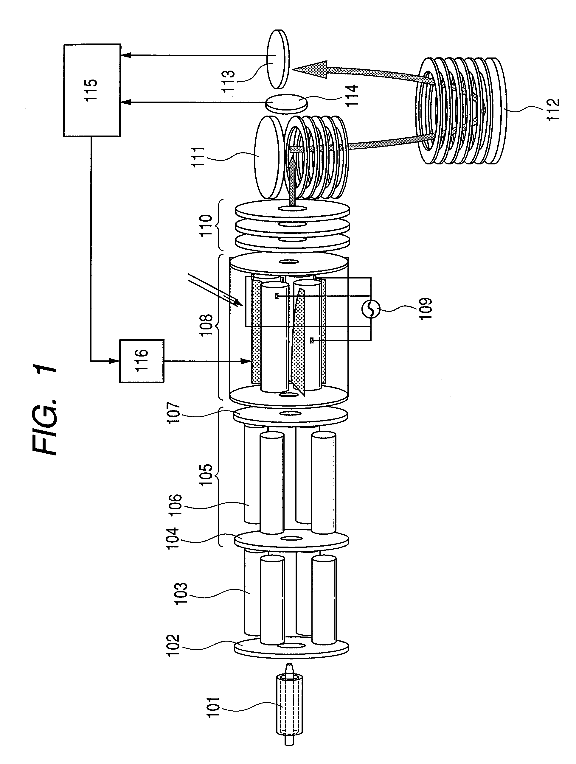
[0034]FIG. 1 illustrates an embodiment of a mass spectrometer that controls ejection time of ions as described above with use of a collisional-damping chamber 108 that includes plural linear quadrupole electrodes that can apply a radio frequency voltage respectively and plural auxiliary electrodes, each being disposed between the linear quadrupole electrodes and capable of applying a DC voltage. Although linear quadrupole electrodes are employed here, they may be replaced with any devices consisting of 4, 6, or 8 rod electrodes respectively and a radio frequency is applied to every other rod of those rod electrodes.

[0035]In FIG. 1, a quadrupole linear ion trap 105 is disposed in the preceding stage of the collisional-damping chamber 108 disclosed in this specification and the time-of-flight mass spectrometer 111-113 are disposed in the succeeding stage of the collisional-damping chamber 108. While a time-of-flight mass spectrometer is employed here, it may be replaced with any detec...

second embodiment

[0048]FIG. 9 shows details of a collisional-damping chamber 901 in still another form. The upper diagram in FIG. 9 shows an external view of another collisional-damping chamber 901 and the lower diagram in FIG. 9 shows a cross sectional view of the collisional-damping chamber 901. The auxiliary electrode 902 of the collisional-damping chamber 901 in this embodiment consists of two parts. One is a metal electrode 903 consisting of a metal conductor that applies an electric field to an object and the other is a resistor or a resistance part 904 having low electrical conductivity and functioning like a resistor electrically. The metal electrode 903 forms a DC potential slope on the center axis of an object quadrupole. The low conductivity resistance part 904 makes a potential difference between both ends of the auxiliary electrode 902. The resistance part 904 is made of a resistor or conductive rubber, an insulator coated with a metal, or the like. Those two parts are connected alterna...

third embodiment

[0053]FIG. 11 is a detailed diagram of a collisional-damping chamber 1101 in still another form. The upper diagram in FIG. 11 is an external view of another collisional-damping chamber 1101 and the lower diagrams are cross sectional views of the collisional-damping chamber 1101. The configuration of the collisional-damping chamber 1101 in this third embodiment is the same as that shown in FIG. 4 except for the auxiliary electrode 1102. The auxiliary electrode 1102 has electrical properties like a resistance material and a dielectric material disposed between a conductor and an insulator. The auxiliary electrode 1102 is made of a material having lower electric conductivity than that of the conductor. This auxiliary electrode 1102 is used to make a potential difference of several mV to several V between both sides of the object. Consequently, this third embodiment can obtain the same effect as that in the first and second embodiments. Furthermore, the same effect can also be obtained ...


PUM


Abstract

A mass spectrometer includes a linear multipole electrode, an auxiliary electrode that applies a DC potential on the center axis of the linear multipole electrode, and a DC power supply that supplies a DC power to the auxiliary electrode. The DC potential slope formed on the center axis of the multipole electrode is changed according to the measuring condition. The ejection time of ions can be adjusted optimally by adjusting the potential slope so as to satisfy the measuring condition. If the ejection time of ions is shortened, confusion of different ion information items that might otherwise occur on a spectrum can be avoided. If the ejection time of ions is lengthened, detection limit exceeding can be avoided and ions can be measured efficiently, thereby highly efficient ion measurements are always assured.

Description

CLAIM OF PRIORITY[0001]The present application claims priority from Japanese patent application JP 2007-185214 filed on Jul. 17, 2007, the content of which is hereby incorporated by reference into this application.FIELD OF THE INVENTION[0002]The present invention relates to a mass spectrometer.BACKGROUND OF THE INVENTION[0003]In case of a mass spectrometry, sample molecules are ionized and introduced into a vacuum chamber or ionized in the vacuum chamber, then the ion movement in an electromagnetic field is measured, thereby measuring the mass charge ratio m / z (m: mass, z: the number of charges) of the object molecular ions. In this case, because what is obtained is a mass-to-charge ratio (m / z), it is difficult to obtain the internal structure information of the object molecular ions, as well. This is why a so-called tandem mass spectrometry is often used. This tandem mass spectrometry carries out the first mass spectrometric operation to identify or select sample molecular ions. Th...

Claims


Application Information

Patent Timeline
IPC IPC(8): B01D59/44
CPCH01J49/004H01J49/427H01J49/4255H01J49/422
Inventor SATAKE, HIROYUKIHASHIMOTO, YUICHIROTAKADA, YASUAKI
Owner HITACHI HIGH-TECH CORP
Why Eureka
Try Eureka