Method and apparatus for reducing current consumption of MIMO systems

a technology of current consumption and mimo system, applied in diversity/multi-antenna system, spatial transmit diversity, gain control, etc., can solve the problems of limiting the tolerable power consumption of wireless portable devices, limiting the output power to certain levels, and reducing the current consumption. , to achieve the effect of increasing the efficiency of a mimo system and reducing the current consumption

Inactive Publication Date: 2009-01-22
QUALCOMM INC
View PDF12 Cites 43 Cited by
  • Summary
  • Abstract
  • Description
  • Claims
  • Application Information

AI Technical Summary

Benefits of technology

[0012]The present invention is directed to a method for reducing the current consumption and increasing the efficiency of a MIMO system, consisting of one or more RF power amplifiers (PAs) and that is required to provide a desired total output power level. An individual output power level which is a portion of the total output power level is determined for each PA. The load, connected to the output stage of each PA, is dynamically or statically tuned to essentially match the output impedance of its output stage, such that its dynamic or static RF load line has a slope that corresponds to the impedance required to provide this portion. Whenever a smaller output power is desired in response to reduction in the input signal to MIMO system, a reduced portion is determined for each PA and the load is further tuned, such that the dynamic / static RF load line has a slope that causes each PA to essentially remain in saturation while providing the reduced portion.
[0013]Wherein whenever only a single PA is activated in the MIMO system, the efficiency of the MIMO system is increased by determining a reduced output power level for the PA, which is a portion of the total output power level. Then the load, connected to the output stage of the PA is dynamically or statically tuned, to essentially match the output impedance of its output stage, such that its dynamic or static RF load line has a slope that corresponds to the impedance required to provide this portion. The PA provides the desired total output power level by enhancing the DC power supplied to the PA, by a level that causes the dynamic or static RF load line to intersect the drain-source voltage at a value being closer to the maximal allowable swing, while essentially keeping its slope.
[0015]The present invention is directed to an apparatus for reducing the current consumption and increasing the efficiency of a MIMO system, consisting of one or more RF power amplifiers (PAs) and that is required to provide a desired total output power level, that comprises:

Problems solved by technology

MIMO systems deliver greater performance, but with additional cost and power consumption.
Thermal and battery life constraints limit tolerable power consumption in wireless portable devices.
Moreover, the wireless standards limit the output power to certain levels.
The requirement to support traditional SISO systems even aggravates the situation.
Current consumption is expected not to change because total transmitting power stays the same, but generally, this is not practical.
An amplifier designed to work at full power in SISO mode, when working at 3-5 dB less power in MIMO modes, leads to 30-55% increase in current consumption of the power amplifiers in the MIMO modes.
Back off from that level reduces efficiency, but is usually required in order to meet output signal linearity conditions.
The power stage has to be designed to handle the highest power leading to very low efficiency at lower output power.
However, using several VEC™ circuits on one board might be expensive and area as well as power consuming.
All the methods described above have not yet provided satisfactory solutions to the problem of efficiently providing power enhancement to several power amplifiers, arranged in a MIMO system.

Method used


Image

  • Method and apparatus for reducing current consumption of MIMO systems
  • Method and apparatus for reducing current consumption of MIMO systems

Examples


examples

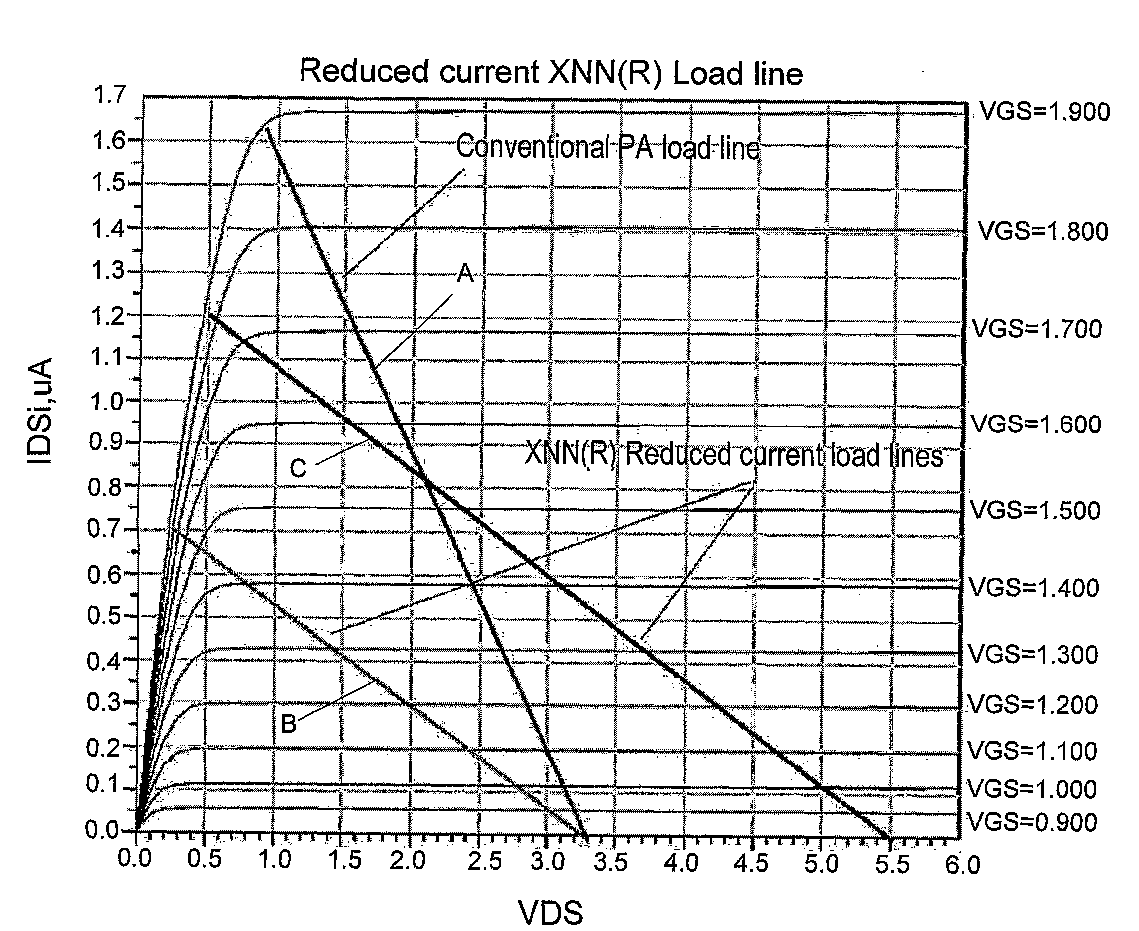
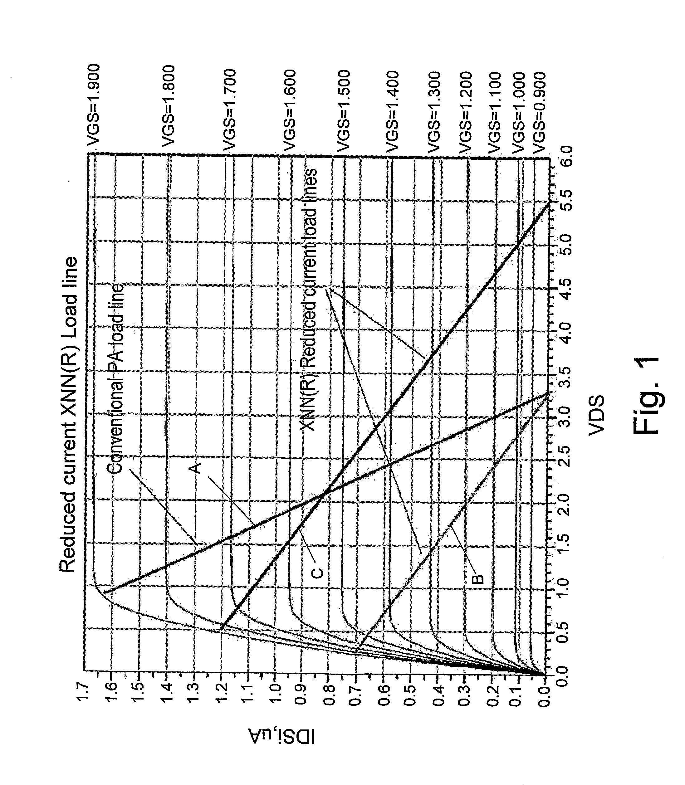
[0028]For specific MIMO system with up to four amplifier arms, the total power has been designed to stay constant for all operational modes, as appears for example, in the Wi-Fi IEEE 802.11n standard. For the case where only one amplifier operates (SISO mode), the power amplifier achieve highest efficiency using XNN® technology. If more arms are operating, the power of each of them is reduced by factor of the number of arms. Each of the MIMO arms was tuned to give maximum efficiency during MIMO operation. An adaptive load line control can be also applied on each of the MIMO arms if required.

[0029]A MIMO W-LAN system working according to the IEEE standard 802.11n with up to four transmit paths is described. Due to the to total output power limitations for systems operating in the unlicensed frequency bands, the total output power of such a MIMO system is limited to 100 mW (20 dBm).

[0030]If there are four Power Amplifiers (PAs) with maximum output power of 20 dBm for each PA, and with...


PUM


Abstract

Apparatus and method for reducing the current consumption and increasing the efficiency of a MIMO system, consisting of one or more RF power amplifiers (PAs) and that is required to provide a desired total output power level. An individual output power level which is a portion of the total output power level is determined for each PA. The load, connected to the output stage of each PA, is dynamically or statically tuned to essentially match the output impedance of its output stage, such that its dynamic or static RF load line has a slope that corresponds to the impedance required to provide this portion. Whenever a smaller output power is desired in response to reduction in the input signal to MIMO system, a reduced portion is determined for each PA and the load is further tuned, such that the dynamic / static RF load line has a slope that causes each PA to essentially remain in saturation while providing the reduced portion.

Description

FIELD OF THE INVENTION[0001]The present invention relates to the field of high efficiency power amplifiers. More particularly, the invention is related to a method for reducing current consumption of RF power amplifiers in MIMO systems without changing their DC supply voltage.BACKGROUND OF THE INVENTION[0002]Traditional wireless communication systems use a single transmission path containing an amplifier and an antenna. Such systems are known as Single Input Single Output (SISO) systems. Multiple Input Multiple Output (MIMO) systems have link budget capacity and throughput superior to SISO systems. MIMO systems deliver greater performance, but with additional cost and power consumption. Thermal and battery life constraints limit tolerable power consumption in wireless portable devices. Moreover, the wireless standards limit the output power to certain levels. The requirement to support traditional SISO systems even aggravates the situation. In SISO mode, the transmitter should deliv...

Claims


Application Information

Patent Timeline
Patent Type & Authority Applications(United States)
IPC IPC(8): H03F1/02
CPCH04B2001/045H04B1/0458H03F1/02H03F3/24H03F1/0205H03F1/0211H03F1/56H04B7/04
Inventor ELIA, AVNER
Owner QUALCOMM INC
Why Eureka
Try Eureka