Process for Producing Metallic Component and Structural Member

a technology of structural components and components, applied in the direction of manufacturing tools, coatings, transportation and packaging, etc., can solve the problems of increasing the surface roughness of the member, unavoidable partial reduction in the degree of improvement in fatigue properties achieved by shot peening, and no deformation. , the effect of excellent fatigue properties

Inactive Publication Date: 2009-01-22
MITSUBISHI HEAVY IND LTD
View PDF4 Cites 2 Cited by
  • Summary
  • Abstract
  • Description
  • Claims
  • Application Information

AI Technical Summary

Benefits of technology

[0024]This structural member has excellent fatigue properties, and has no deformation such as bending and no excessive surface roughness. Furthermore, because production can be performed without the need for covering with a pressure-sensitive adhesive mask and without chamfering or rounding of the edges, the structural member can be produced at a reduced cost. This structural member can be used favorably in the field of transportation machinery such as aircraft and automobiles, and in other fields that require favorable material fatigue properties.
[0025]The present invention provides a process for producing a metallic component of a structural member or the like used in an aircraft or automobile or the like, the process comprising shot peening the surface of a metallic material, wherein the fatigue properties of the metallic material can be improved with almost no variation in the surface roughness over the course of shot peening.
[0026]Furthermore, the present invention also provides a process for producing a metallic component of a structural member or the like used in an aircraft or automobile or the like, the process comprising shot peening the surface of a metallic material, wherein by reducing deformation of the metallic material and suppressing increases in the surface roughness, covering of the metallic material surface becomes unnecessary, and the metallic component can be produced at a reduced cost.
[0027]Moreover, the present invention also provides a process for producing a metallic component of a structural member or the like used in an aircraft or automobile or the like, the process comprising shot peening the surface of a metallic material, wherein chamfering or rounding of edges prior to shot peening is unnecessary, enabling reductions in the number of process steps and the production costs.

Problems solved by technology

However, shot peening increases the surface roughness of the member, meaning the prescribed surface roughness required for a particular application may not always be attainable.
Furthermore, because of the increase in surface roughness and the effect of flaws generated on the surface of the member by the shot, a partial reduction in the degree of improvement in fatigue properties achieved by shot peening is unavoidable.
On the other hand, flapper peening does not induce a high level of compressive residual stress, and as a result, satisfactory fatigue properties cannot be obtained.
Furthermore, cold working processes require post-processing, meaning the process is more complex.
Moreover, shot peening may also cause plastic deformation of the surface layer of the member, which can cause deformation problems such as bending.
However, attaching and then removing a pressure-sensitive adhesive mask requires considerable effort, and results in extra costs.
Moreover, when shot peening, if a shot particle strikes an edge of the member, then plastic deformation at the edge can cause a portion to fly off the member, generating a so-called burr.
However, chamfering or rounding of the edges is typically performed manually, meaning the efficiency is poor.

Method used


Image

  • Process for Producing Metallic Component and Structural Member
  • Process for Producing Metallic Component and Structural Member
  • Process for Producing Metallic Component and Structural Member

Examples


example 1 and example 2

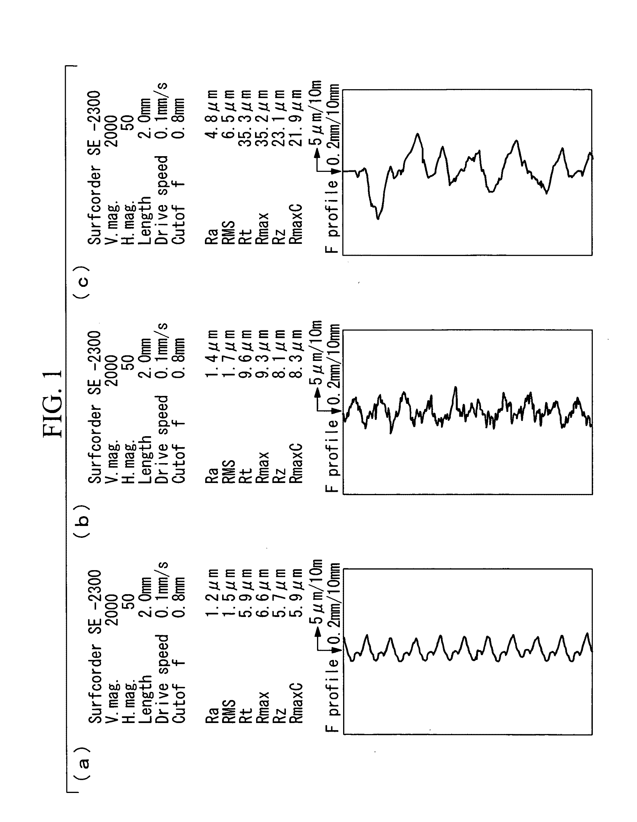
[0047]A sheet of an aluminum alloy material (7050-T7451, dimensions: 19 mm×76 mm×2.4 mm) was used as a test specimen. One surface of this specimen was shot peened using a shot material composed of alumina / silica ceramic particles with an average particle size (most frequent particle size) of not more than 50 μm, under conditions including an air pressure of 0.4 MPa and a spray time of 30 seconds.

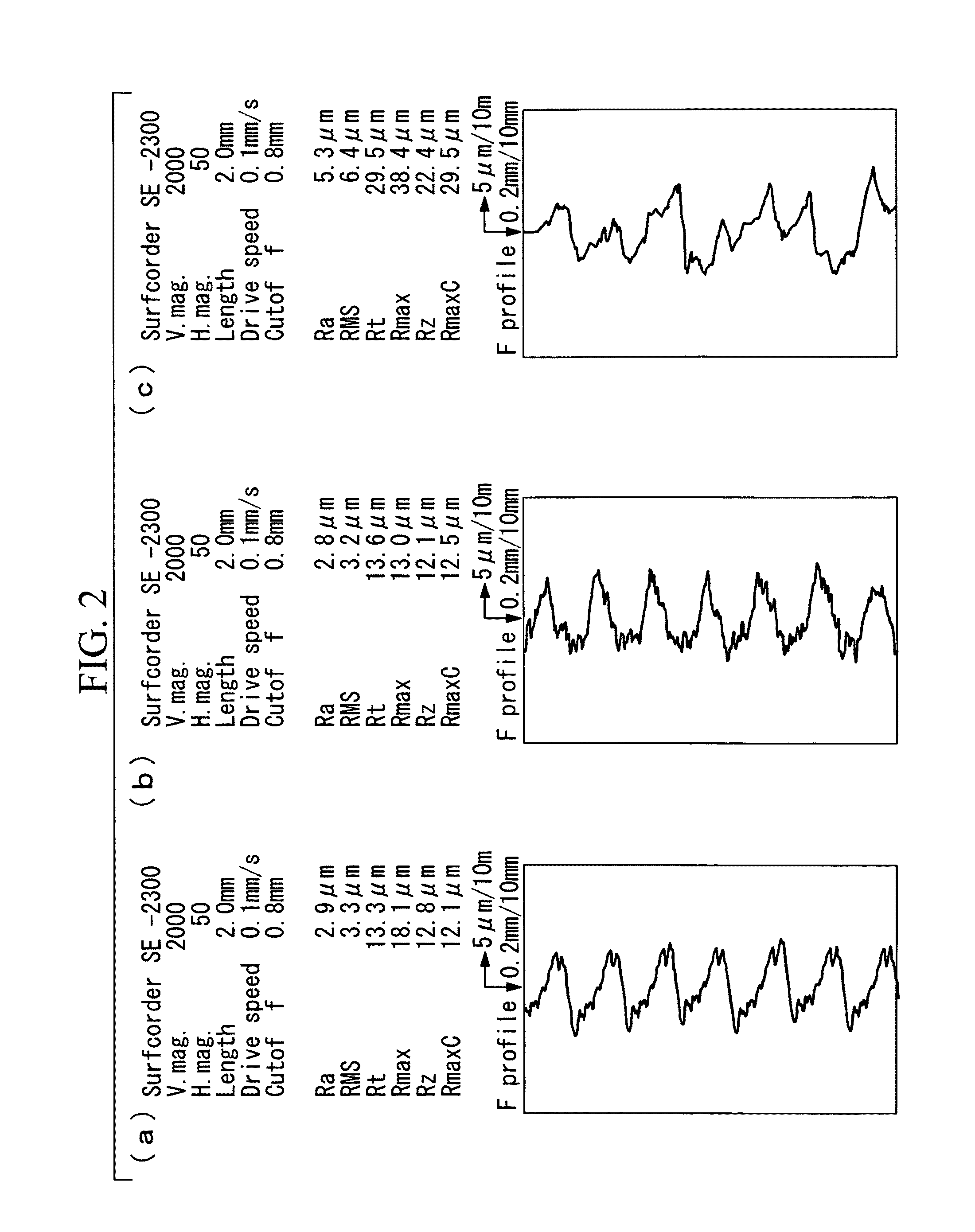
[0048]Two aluminum alloy materials having different surface roughness values were prepared as the pre-shot peening materials. In Example 1, an aluminum alloy material with a surface roughness of 1.2 μm prior to shot peening was used, whereas in Example 2, an aluminum alloy material with a surface roughness of 2.9 μm prior to shot peening was used.

[0049]A dynamic microparticle shot apparatus (model number: P-SGF-4ATCM-401, manufactured by Fuji Manufacturing Co., Ltd.) was used as the shot peening apparatus.

[0050]Following shot peening, the surface roughness, compressive residual stress, and d...

example 3 and example 4

[0056]With the exception of replacing the test specimen with a sheet of a titanium alloy material (Ti-6Al-4V (an annealed material), dimensions: 19 mm×76 mm×2.4 mm), shot peening in Example 3 and Example 4 was performed in the same manner as in Example 1 and Example 2, respectively.

[0057]Two titanium alloy materials having different surface roughness values were prepared as the pre-shot peening materials. In Example 3, a titanium alloy material with a surface roughness of 1.64 μm prior to shot peening was used, whereas in Example 2, a titanium alloy material with a surface roughness of 3.2 μm prior to shot peening was used.

[0058]The conditions for shot peening in Example 3 and Example 4, the surface roughness values for the test specimens before and after shot peening, and the compressive residual stress, surface roughness, degree of deformation and fatigue life of the test specimens following shot peening are shown in Table 1. The fatigue life was evaluated by performing a tension-...

example 5

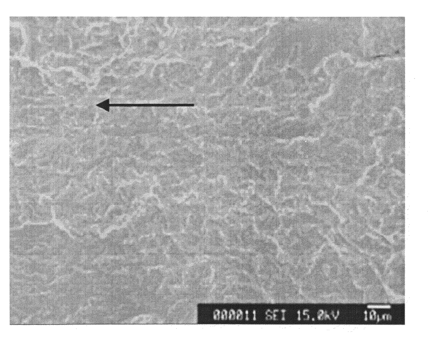
[0062]The area around the hole within a test specimen composed of a flat sheet of a titanium alloy (Ti-6Al-4V (an annealed material)) with a hole formed therein was shot peened in the same manner as Example 3. No processing such as chamfering or rounding of the hole edges was performed prior to shot peening. Following a fatigue test, the fatigue fracture surface was inspected using an electron microscope. FIG. 6 is an electron microscope photograph of the fatigue fracture surface of the specimen from Example 5. In the figure, the arrow indicates the fatigue fracture origin.

[0063]From the electron microscope photograph of FIG. 6 it is evident that the fatigue fracture origin is several tens of μm inside the inner surface of the hole within the specimen of Example 5.

[0064]The results of performing a fatigue test (a tension-tension fatigue test, stress ratio R=0.1) using the above hole-containing flat sheet are shown in Table 2. It is clear that despite the fact that no processing such...


PUM

PropertyMeasurementUnit
particle sizeaaaaaaaaaa
surface roughnessaaaaaaaaaa

Abstract

A process for producing a metallic component of a structural member or the like used in an aircraft or automobile or the like, the process including shot peening the surface of a metallic material, wherein the fatigue properties of the metallic material are improved with almost no variation in the surface roughness over the course of shot peening. Shot peening the metallic material surface uses a shot material having an average particle size of not more than 200 μm, and the ratio of the surface roughness of the metallic material surface following the projection step relative to the surface roughness of the metallic material surface prior to the projection step is not less than 0.8 and not more than 1.5.

Description

TECHNICAL FIELD[0001]The present invention relates to a process for producing a metallic component having improved fatigue properties and a structural member.BACKGROUND ART[0002]Shot peening represents a known example of a surface modification process that is used for enhancing the fatigue strength of metallic materials such as the structural members used in aircraft and automobiles and the like (see Non Patent Citation 1). Shot peening is a method in which, by blasting countless particles having a particle size of around 0.8 mm (the shot material) together with a stream of compressed air onto the surface of a metallic material, the hardness of the metallic material surface is increased, and a layer having compressive residual stress is formed at a certain depth.[0003]Furthermore, other techniques such as flapper peening and cold working are also used as methods of enhancing the fatigue strength of a metallic material.[0004]Non Patent Citation 1: T. Dorr and four others, “Influence ...

Claims


Application Information

Patent Timeline
Patent Type & Authority Applications(United States)
IPC IPC(8): C21D7/06B32B33/00B24C1/10
CPCB24C1/10B24C11/00Y10T428/12993Y10T29/479C21D7/06
Inventor OGURI, KAZUYUKISEKIGAWA, TAKAHIROINOUE, AKIKO
Owner MITSUBISHI HEAVY IND LTD
Why Eureka
Try Eureka