
Method for soldering two components together by using a solder material

a technology of soldering material and component, applied in the field of microelectronics, can solve the problems of inherently corroding flux of solder flux, impairment of sought-after hybridization between chip b, and worsening undesirable corrosion, so as to prevent the electrochemical reaction inherent in the different redox potentials

Inactive Publication Date: 2009-01-29
COMMISSARIAT A LENERGIE ATOMIQUE ET AUX ENERGIES ALTERNATIVES +1
View PDF2 Cites 5 Cited by
  • Summary
  • Abstract
  • Description
  • Claims
  • Application Information

AI Technical Summary

Benefits of technology

[0036]deoxidizing and limiting the reoxidation of said solder material after actually producing said soldered joint, transferring heat and reducing the surface tension;
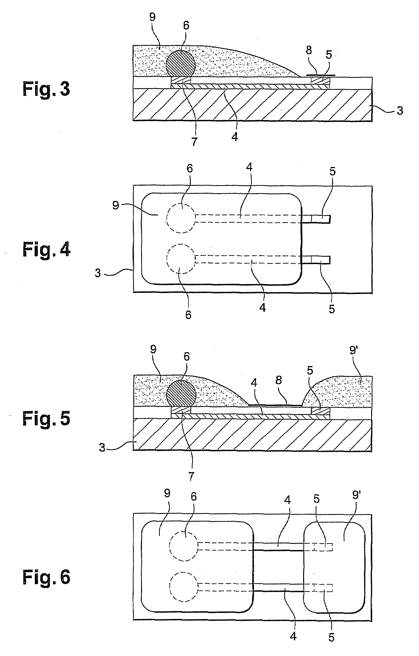
[0040]In other words, the invention involves creating an electrical discontinuity at the level of the solder flux between a specific area where the solder material is positioned and the external bonding pads, in order to prevent the electrochemical reaction which is inherent in the different redox potentials of the metals used.

Problems solved by technology

Generally speaking, these solder fluxes are inherently corrosive and after oxide reduction are also capable of attacking the actual solder metal.
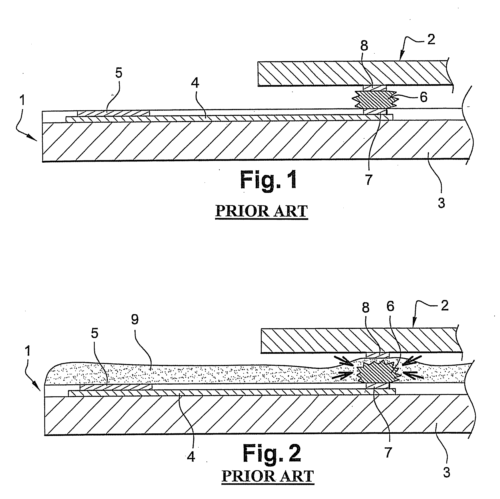
Experience shows that this undesirable corrosion is made worse by two particular configurations:a galvanic effect resulting from the use of a pair of metals having different electrochemical potentials in the presence of solder flux, the latter acting as an electrolyte;the solder bumps and the flux remaining in contact for an excessively long time.
This being so, reduction of the material which constitutes the bump is observed and this results in it being dissolved, at least partially, in the solder flux and, consequently, impairment of the sought-after hybridization between chip 2 and component 1.
However, both these solutions make the process of fabricating the host circuit, in this case the component, more complex, not only because of an additional stage which results in reduced fabrication yields, but also because of higher fabrication costs.
In both cases, cathodic protection makes the fabrication process more complex and, in the latter case, makes the management of signal inputs and outputs more complicated.
It should, however, be emphasized that this technical problem which is inherent in the electrochemical consumption of the material that constitutes the hybridization bumps, is not actually critical if hybridization as such can be performed in a shorter time.
The corresponding hybridization sequence may then last several hours and, given this fact, the electrochemical corrosion or consumption phenomena described above can no longer be tolerated because they worsen over time.
These temperature rises can be disadvantageous, the reader being reminded that, for indium, a thermal soldering cycle with a brief peak at 170-180° C. is sufficient.

Method used


Image

  • Method for soldering two components together by using a solder material
  • Method for soldering two components together by using a solder material
  • Method for soldering two components together by using a solder material

Examples


Embodiment Construction

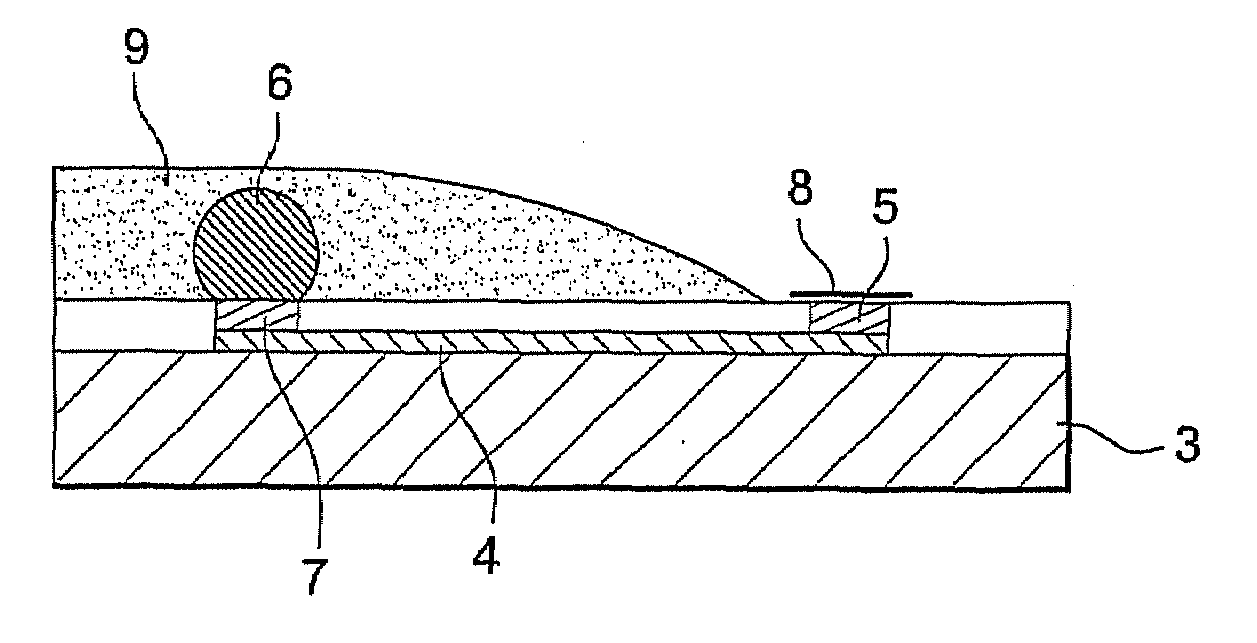
[0049]The hybridization method according to the invention is described more especially in relation to FIGS. 3 to 6.

[0050]These show the hybridization of a chip 2 on an electronic component 1. As in the description of FIGS. 1 and 2, this component fundamentally comprises a substrate 3 which is also referred to as the host substrate. This is typically made of a semiconductor material, especially monocrystalline silicon. On this substrate 3 there are a number of conductors 4 designed, in this case, to allow the transmission of electric signals from chip 2 to the external environment with a view to processing them. These conductors are, for instance, made of aluminum and lead to one or more external bonding pads 5.

[0051]Such external bonding pads require the use of a localized layer which encourages electrical conduction and, in this case, consists of a gold wire.

[0052]The hybridization bumps which ensure connection and interfacing and are also referred to as “useful bumps” are typicall...


PUM

PropertyMeasurementUnit
temperatureaaaaaaaaaa
contact angleaaaaaaaaaa
metallicaaaaaaaaaa

Abstract

A method for soldering or hybridizing two components to each other by means of a solder material, including producing, on the opposite-facing surfaces of the components to be soldered or hybridized, a surface capable of being wetted by said solder material, this surface being produced on a first component which is in electrical contact with a metallic conductor, depositing an appropriate quantity of solder material capable of constituting a solder or hybridization pad on one of the wettability surfaces, depositing a flux material in liquid form, bringing the wettability surface of the other component into contact with the solder material thus deposited and raising the temperature until at least the melting temperature of the solder material is reached in order to ensure effective soldering or hybridization of the two components to each other due to the reflow effect.

Description

FIELD OF THE INVENTION[0001]The present invention relates to the field of microelectronics and, more especially, techniques for the hybridization of two different components using interconnection bumps which are also referred to as “solder bumps”. The invention therefore relates to the general field of microcomponents, more conventionally referred to as a chips, but it also has applications for microsensors, microactuators such as Micro-Electro-Mechanical Systems (MEMS) and optoelectronic components of the semiconductor Vertical Cavity Surface Emitting Laser (VCSEL) type, etc.[0002]Within the meaning of the invention, the term “component” is understood to be an electronic sensor such as a chip, a mounting structure for an electric or electronic circuit or a passive electrical component of the integrated-circuit lid type or even a sensor for characterizing a physical quantity.DESCRIPTION OF THE PRIOR ART[0003]The microcomponents in question dealt with in the context of the present in...

Claims


Application Information

Patent Timeline
Patent Type & Authority Applications(United States)
IPC IPC(8): B23K1/20C23C16/30
CPCB23K1/0016B23K1/203H01L2924/1461H01L2224/0401H01L2224/48644H01L2924/01075H01L2924/01033H01L2924/01006H01L2224/0558H01L2924/19107H01L2924/14H01L2924/01082H01L2924/01079H01L2924/01058H01L2924/01057H01L2924/0105H01L23/147H01L24/13H01L24/81H01L2224/05644H01L2224/13109H01L2224/13111H01L2224/16H01L2224/26175H01L2224/45144H01L2224/81011H01L2224/81192H01L2224/812H01L2224/8121H01L2224/81815H01L2924/01004H01L2924/01013H01L2924/01014H01L2924/01049H01L2924/00014H01L2924/01047H01L2924/01029H01L2924/00
Inventor KOPP, CHRISTOPHEBABLET, JACQUELINERABY, JACQUESROSSAT, CYRILLE
Owner COMMISSARIAT A LENERGIE ATOMIQUE ET AUX ENERGIES ALTERNATIVES
Learn More