Multi Beam Photonic Beamformer

Inactive Publication Date: 2009-01-29
COWARD JAMES F
View PDF5 Cites 27 Cited by
  • Summary
  • Abstract
  • Description
  • Claims
  • Application Information

AI Technical Summary

Benefits of technology

[0010]The present invention is particularly advantageous because current true time delay beamformer technology has very high optical loss driving up system power and degrading system spur free dynamic range. The present invention provides a large range o

Problems solved by technology

They also degrade gracefully due to the large number of antenna element.
First, microwave switches are lossy, have high crosstalk, and are lack of good impedance matches—all of which will lead to a lower antenna sensitivity.
Secondly, this PTDU generates only one delayed signal making multiple simultaneous microwave beam operation of a single antenna impossible.
Thirdly, it requires a separate PTDU per sub-array per microwave beam.
Although MEMs switches have low optical loss, they do have slow switching time.
Electro-optic switches are fast but costly and high optical loss.
But they have optical loss on the order of sev

Method used


Image

  • Multi Beam Photonic Beamformer
  • Multi Beam Photonic Beamformer
  • Multi Beam Photonic Beamformer

Examples


Embodiment Construction

Introduction

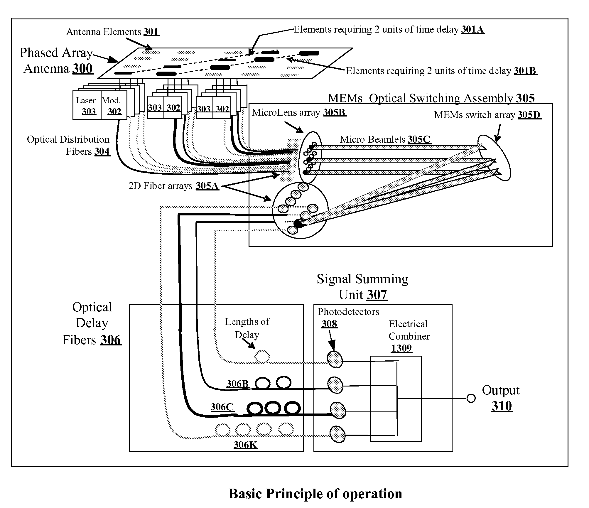
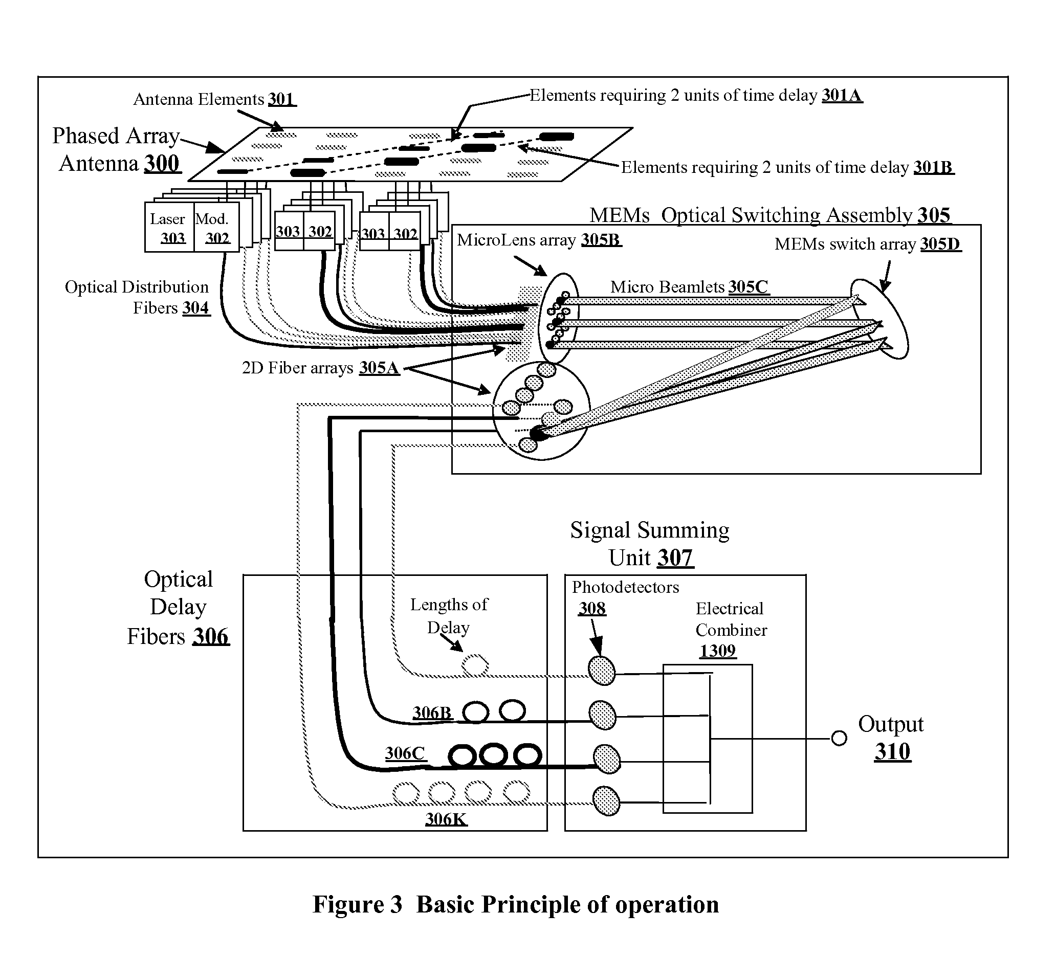
[0023]The basic concept for the antenna receive function is shown in FIG. 3. The present invention is for beamforming for phased array antennas. The phased array antenna 300 receives the incident RF / microwave energy. Antenna elements 301 convert the energy from the impinging RF / microwave beam into an electrical signal that drives the optical modulator 302. An optical laser source 303 provides continuous wave (CW) optical power to the modulator. The optical modulator converts the CW optical power into a optically modulated signal corresponding to the electrical drive signal from the antenna element. The modulated optical signal is transported via optical distribution fiber 304 to the MEMs optical switch assembly 305 (MOSA). For an antenna with M antenna elements, there would be M optical modulators and M optical fibers.

[0024]The MOSA has M input fibers. The output of the MOSA is attached to optical delay fibers 306. The number of delay fibers, K, varies from one beamforme...


PUM


Abstract

A true time delay beamformer for RF/microwave phased array antenna systems using multiple laser sources, optical modulators to convert the electrical signal to a modulated optical signal, standard optical fiber for creating time delays, dispersive optical fiber for creating delays, optical splitting and/or switching section, photodetectors to convert the modulated optical signal to an electrical signal, and a signal combining section. The true time delay beamformer has the capability to create multiple simultaneous RF/microwave antenna beams. One (more lasers) is used to source one (or more) wavelengths of light to the optical modulator. The signal from one (or more) antenna elements drive the optical modulator. The light from the optical modulator passes through the standard optical fibers and/or the dispersive optical fibers to create time delay variation for one optical modulator relative to another allowing for the formation of RF/microwave beams. Fixed location RF/microwave beams can be generated by a static network of standard and/or dispersive optical delay fibers. Steering of the location of the RF/microwave beams can be accomplished by an optical switching mechanism which could be based on MEMs and/or wavelength routing based switching. Finally, all the signals for a RF/microwave beam are summed to form a single output. The summing can occur either optically before the photodetectors and/or electrically after the photodetectors.

Description

BACKGROUND OF THE INVENTION[0001]1. Field of the Invention[0002]This invention relates generally to true time delay beamformer networks for RF / microwave / millimeter wave phased array antenna systems[0003]2. Description of the Related Art[0004]Phased-array antennas are becoming important elements in modem radar and communication systems. Phased-array antennas have many important advantages. They are capable of steering microwave beams quickly without physically moving the antennas; making two-dimensional steering with ease; receiving and transmitting multi-beams simultaneously; and controlling beam width and sidelobe power. They also degrade gracefully due to the large number of antenna element.[0005]The generalized functional block diagram for an electronically steered phased array antenna is shown in FIG. 1. Each antenna radiating element typically has an associated transmit / receive (T / R) Module. The antenna elements and associated T / R modules are generally combined into sub-arrays....

Claims


Application Information

Patent Timeline
IPC IPC(8): H01Q3/22
CPCH01Q3/2676H01Q3/22
Inventor COWARD, JAMES F.
Owner COWARD JAMES F
Why Eureka
Try Eureka