Method and apparatus for performing optical imaging using frequency-domain interferometry

a frequency-domain interferometer and optical imaging technology, applied in the field of optical imaging, can solve the problems of low imaging frame rate, poor depth of penetration, non-optimal resolution, etc., and achieve the effect of suppressing relative intensity noise, achieving gain in signal-to-noise ratio (“snr”), and reducing nois

Active Publication Date: 2009-01-29
THE GENERAL HOSPITAL CORP
View PDF99 Cites 40 Cited by
  • Summary
  • Abstract
  • Description
  • Claims
  • Application Information

AI Technical Summary

Benefits of technology

[0012]With such exemplary particular arrangement, an OFDI system which can operate with source powers that are relatively low compared with source powers of conventional systems and / or which operate at acquisition rates which are relatively high compared with acquisition rates of conventional systems may be provided. The use of a swept source results in an imaging system having reduced shot noise and other forms of noise which allows for much lower source powers, or much higher acquisition rates than conventional systems. This can lead to an increased detection sensitivity which results in the ability to provide real time imaging. Such imaging speed can assist practitioners in gastrointestinal, ophthalmic and arterial imaging fields, where motion artifacts are a continuing problem. By increasing a frame rate while maintaining or improving the signal to noise ratio such artifacts can be minimized or in some cases eliminated. Exemplary embodiments of the present invention may also enable the screening of large areas of tissues with OFDI and allows enables the use of clinically viable screening protocols.
[0018]For ophthalmic applications of OFDI, efficient detection preferably allows for a significant increase of acquisition speed. One limitation in ophthalmic applications is the power that is allowed to enter the eye according to the ANSI standards (approximately 700 microwatts at 830 nm). Current data acquisition speed in ophthalmic applications is approximately 100-500 A-lines per second. The power efficient detection technique of the present invention would allow for A-line acquisition rates on the order of about 100,000 A-lines per second, or video rate imaging at about 3,000 A-lines per image.

Problems solved by technology

Multiple variants of the OCT techniques have been described, but many suffer from less than optimal signal to noise ratio (“SNR”), resulting in non-optimal resolution, low imaging frame rates, and poor depth of penetration.
Thus, boosting power is not feasible to increase SNR in such environments.
There are, however, a number of disadvantages associated with using a CCD device.
First, CCD devices are relatively expensive compared to a single-element photo-receiver.
Secondly, the previously described method uses a single CCD to acquire the data.
Since the charge storage capacity is limited, it requires a reduction of the reference arm power to approximately the same level as the sample arm power, giving rise to auto correlation noise on the sample arm light.
In addition, since no carrier is generated, the 1 / f noise will dominate the noise in this system.
Thirdly, even with the short integration times of state of the art CCD technology, phase instabilities in the interferometer reduce fringe visibility of the cross spectral density modulation.
This shortcoming makes the technique vulnerable to motion artifacts.

Method used


Image

  • Method and apparatus for performing optical imaging using frequency-domain interferometry
  • Method and apparatus for performing optical imaging using frequency-domain interferometry
  • Method and apparatus for performing optical imaging using frequency-domain interferometry

Examples


Embodiment Construction

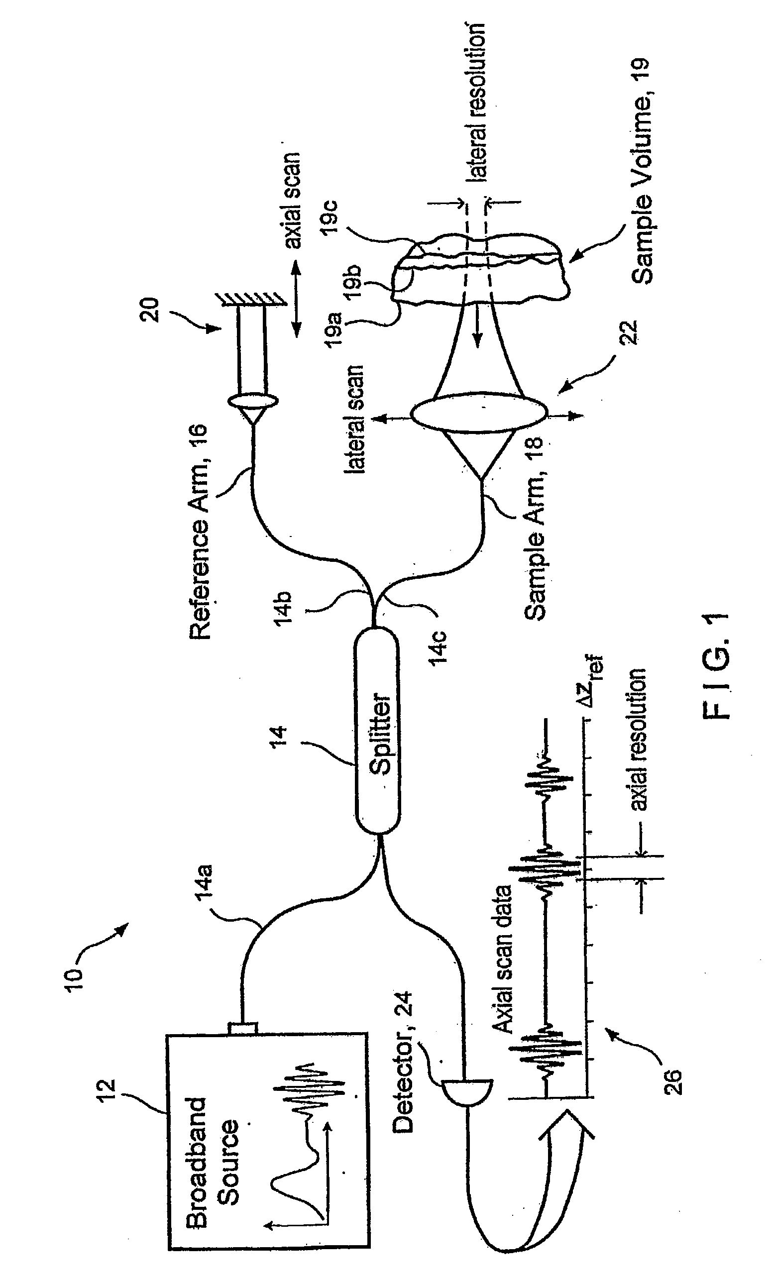
[0056]FIG. 1 shows an exemplary prior art time domain optical coherence tomography (“OCT”) system 10 which includes a broadband source 12 that provides a signal to a first arm 14a of two-by-two splitter 14. The splitter divides the signal provided thereto at port 14a, and provides a first portion of the signal at a port 14b coupled to a reference arm 16. The splitter 14 also provides a second portion of the signal at a port 14c coupled to a sample arm 18.

[0057]The sample arm 18 terminates at a sample volume 19 and an arrangement 22 for providing a lateral scan of the sample volume is disposed in the sample arm 18 prior to the sample volume 19. The reference arm 16 terminates in an arrangement 20 for providing an axial scan. The arrangements 20 and 22 operate as is generally known in the art.

[0058]Signals reflected from the means 20 and sample volume 19 back along the reference and sample arms 16, 18 respectively, are coupled back into respective ports 14b, 14c of the splitter 14 and...


PUM

PropertyMeasurementUnit
tuning wavelength rangeaaaaaaaaaa
poweraaaaaaaaaa
structureaaaaaaaaaa

Abstract

An apparatus and method are provided. In particular, at least one first electro-magnetic radiation may be provided to a sample and at least one second electro-magnetic radiation can be provided to a non-reflective reference. A frequency of the first and / or second radiations varies over time. An interference is detected between at least one third radiation associated with the first radiation and at least one fourth radiation associated with the second radiation. Alternatively, the first electro-magnetic radiation and / or second electro-magnetic radiation have a spectrum which changes over time. The spectrum may contain multiple frequencies at a particular time. In addition, it is possible to detect the interference signal between the third radiation and the fourth radiation in a first polarization state. Further, it may be preferable to detect a further interference signal between the third and fourth radiations in a second polarization state which is different from the first polarization state. The first and / or second electro-magnetic radiations may have a spectrum whose mean frequency changes substantially continuously over time at a tuning speed that is greater than 100 Tera Hertz per millisecond.

Description

CROSS REFERENCE TO RELATED APPLICATION(S)[0001]This application claims priority from U.S. provisional application No. 60 / 514,769 filed on Oct. 23, 2003, the entire disclosure of which is incorporated herein by reference.FIELD OF THE INVENTION[0002]The present invention relates generally optical imaging, and more particularly to method and apparatus for performing optical imaging using frequency-domain interferometry.BACKGROUND OF THE INVENTION[0003]As is known in the art, optical interferometric reflectometry is a powerful tool for performing non-invasive, high-resolution (˜10 μm), cross-sectional imaging of a biological or other sample, to visualize micro-structural optical properties such as reflection, absorption, scattering, attenuation, birefringence, and spectroscopic analysis. There are a number of interferometric imaging techniques that are known in the art. These techniques in general can be divided into two major categories: (i) time-domain technique, and (ii) frequency-do...

Claims


Application Information

Patent Timeline
Patent Type & Authority Applications(United States)
IPC IPC(8): G01B11/02A61B5/00G01J9/02G01N21/47G02B27/48
CPCA61B5/0059G01B9/02084A61B5/7257G01J3/02G01J3/0208G01J3/021G01J3/0218G01J3/0264G01J3/453G01J9/0215G01N21/4795G02B27/48H01S3/08009H01S3/08063H01S3/105H01S5/141H01S5/146G01B9/02004G01B9/02002G01B9/0209G01B9/02091G01B2290/70G01B9/02081G01B2290/45G01B9/02083G01B9/02043G01B9/02075A61B5/0066G02F1/093G02F1/11G01J9/02G01J9/00G01B9/02A61B5/00H01S5/0071H01S5/14H01S5/1025H01S3/1068H01S5/0078H01S5/5045G02B6/3604G02B26/12H01S3/0071H01S3/0078
Inventor YUN, SEOK-HYUNBOUMA, BRETT EUGENETEARNEY, GUILLERMO J.DE BOER, JOHANNES FITZGERALD
Owner THE GENERAL HOSPITAL CORP
Why Eureka
Try Eureka