Perpendicular Magnetic Recording Medium, and Perpendicular Magnetic Recording and Reproducing Apparatus

Inactive Publication Date: 2009-02-05
TOHOKU UNIV +2
View PDF6 Cites 7 Cited by
  • Summary
  • Abstract
  • Description
  • Claims
  • Application Information

AI Technical Summary

Benefits of technology

[0053]In this invention, a pinning layer and / or a non-magnetic underlayer can be used, but, there is no influence on the effect of the invention without these layers. In this invention, it is necessary that Kugrain of the SUL has a negative value. When CoIr is used as a soft magnetic layer material, it is necessary to make the C axis of hcp CoIr crystal perpendicular to the substrate surface plane. An underlayer is sometimes provided to control crystal orientation. In this case, usually, the underlayer has also an hcp crystal structure, such as Ti and Ru.
[0054]We found that it is suitable for Kugrain of SUL to have a negative value in the axis perpendicular to the substrate surface plane.
[0056]A perpendicular magnetic anisotropic energy, Ku⊥, is estimated by extrapolation for 2θ components of the toque to the saturation field. The toque curve is obtained by rotating the magnetic field in the plane perpendicular to the substrate surface plane of the coupon sample.
[0057]Kugrain is calculated using the relationship Ku⊥=−2πMs2+Kugrain (Ms: saturation magnetization), for a SUL in which the C axis of the uniaxial crystal magnetic anisotropy is perpendicular to the substrate surface plane.
[0058]It is known that a film sample has a strong demagnetizing field perpendicular to the film plane, and at that time Ku⊥ is expressed as −2πMs2. This invention has an objective to provide a SUL such that X has a negative value if Ku⊥ is expressed −2πMs2+X .
[0059]In the case of a conventional SUL, X usually has a small positive value due to defects and impurities. In this invention, large |Ku⊥| forces the magnetization to be directed to the surface by making X a negative number. In addition, the fluctuation of the magnetization by environmental field can be decreased because an energy state becomes more stable when making the direction of magnetization in the substrate surface plane.

Problems solved by technology

When the SUL (soft magnetic underlayer) of perpendicular magnetic recording media is deposited, there exist the following problems.
(1) It is difficult to control the magnetic field uniformly in the entire radial direction.
As media sizes will continue to be smaller in the future, (2) becomes a serious problem.

Method used


Image

  • Perpendicular Magnetic Recording Medium, and Perpendicular Magnetic Recording and Reproducing Apparatus
  • Perpendicular Magnetic Recording Medium, and Perpendicular Magnetic Recording and Reproducing Apparatus
  • Perpendicular Magnetic Recording Medium, and Perpendicular Magnetic Recording and Reproducing Apparatus

Examples


example 1

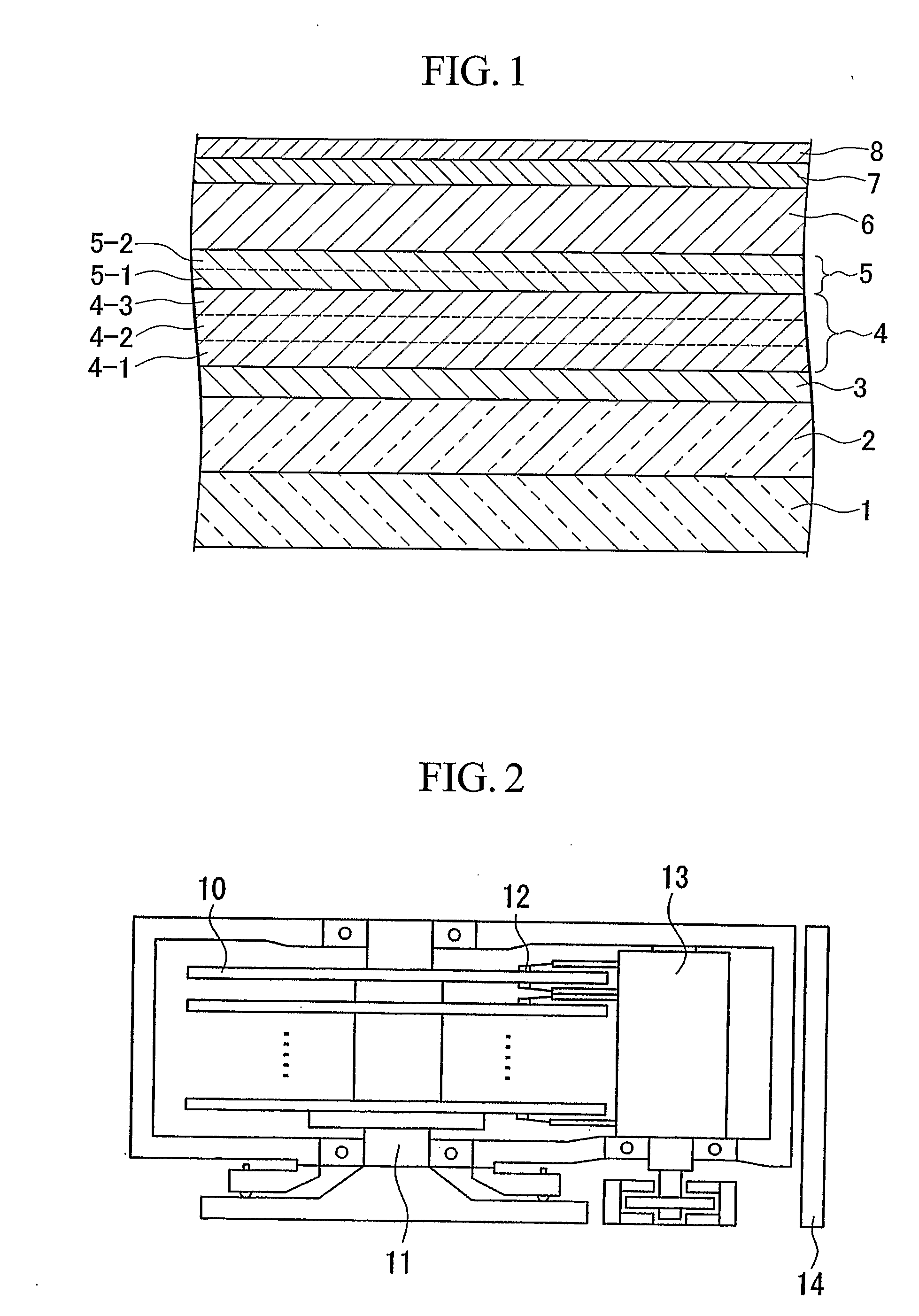
[0082]After washing the glass substrate (crystallized substrate TS10-SX, diameter 2.5 inches, manufactured by Ohara Inc.), the glass substrate was placed in the film deposition chamber of a DC magnetron sputtering system (Anelva Corp. model C-3010), and the film deposition chamber was evacuated to a background pressure of 1×10⁻⁵ Pa. On this glass substrate 7 nm of a Ti layer was deposited. Then 3 nm of Ru, and 20 nm of 88Co-12Ir (Co content 88 at. %, Ir content 12 at. %) were deposited, to form a SUL with a double-layers structure.

[0083]On this sample 6 nm of a Pd seed layer, 20 nm of a Ru intermediate layer, 10 nm of a CoCrPt—SiO2 magnetic recording layer, and 5 nm of a C protective layer were deposited by sputtering method. Then, a dipping method was used to form a lubrication layer of perfluoro-polyether, to obtain the perpendicular magnetic recording media.

examples 2 to 6

, Comparison Examples 2 to 6

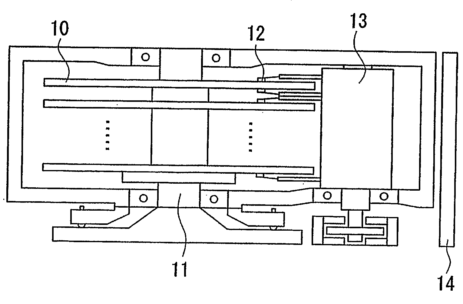
[0095]Next, a perpendicular recording medium similar to that for Example 1 and Comparison Example 1 was prepared, using a silicon substrate of radius 22 mm as a substrate. In the depositing process, 5 pieces of substrate were subjected to film deposition simultaneously. Five pieces of sample were prepared by the same process as in Example 1 and the other 5 pieces of sample by the same process as in Comparison Example 1. The arrangement of the substrates during the deposition process is shown in FIG. 5.

[0096]Examples 2 to 6 were similar to Example 1 and Comparison Examples 2 to 6 were similar to Comparison Example 1.

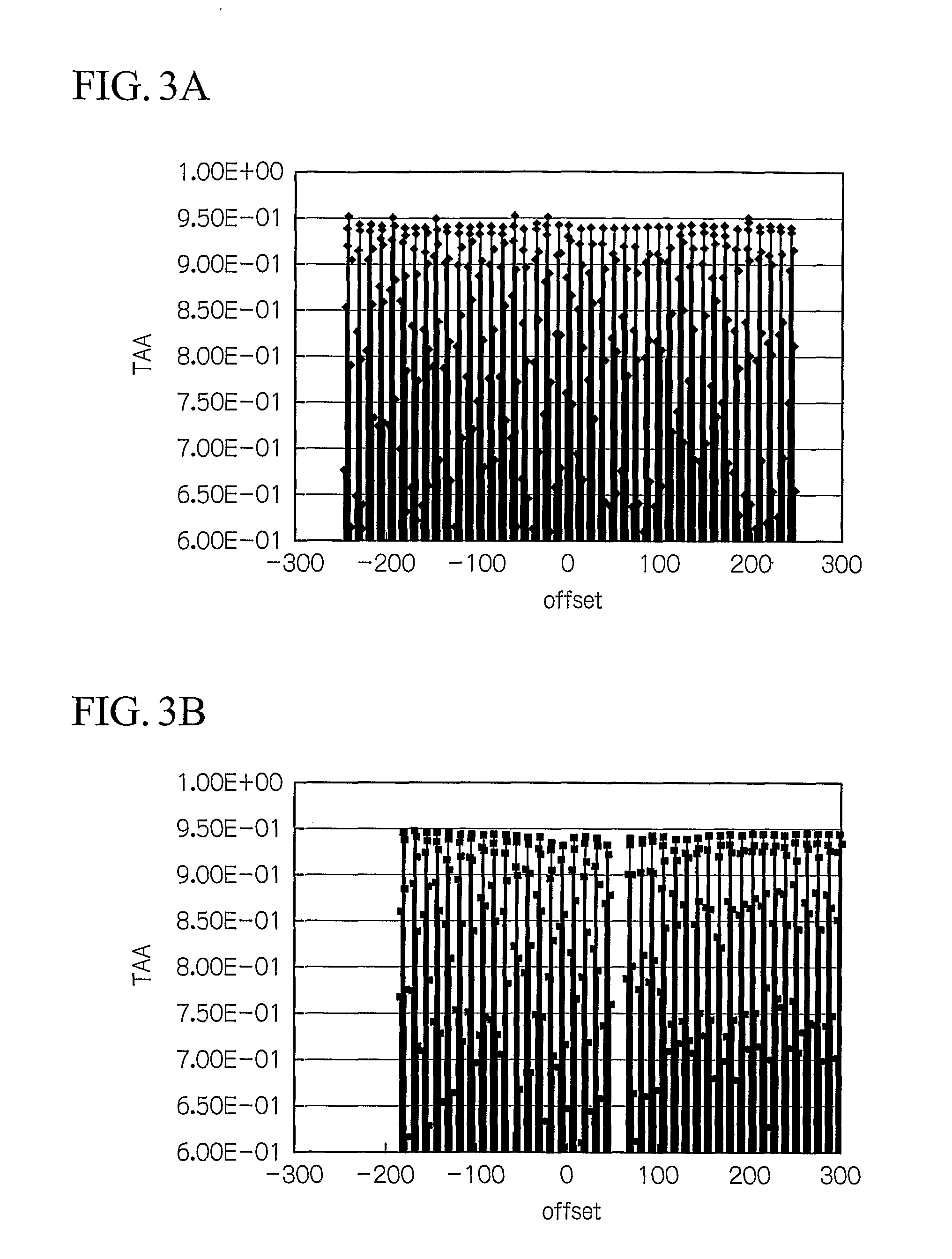
[0097]WATE measurements which are the same as those in Example 1 and Comparison Example 1 were performed for the above samples. The dependence of the WATE phenomena on the positions of the substrates was also estimated. The results are shown in Table 2.

TABLE 2SoftCrystalmagneticstructure ofOutputunderlayersoft magneticKugrainKu⊥−2πMs2reductionU...

example 7

[0100]A special vacuum chamber of the magnetron sputtering system (Anelva Corp. model C-3010) which has two rotatable targets was used for co-sputtering experiment of two different materials on the crystallized glass substrates. The chamber was evacuated to a background pressure 1×10⁻⁵ Pa. As two target materials, a pure Co and a pure Ir were used.

[0101]First, the crystallized glass substrate was heated to 350° C. using a lamp heater. Next, a Ti film of 7 nm and a Ru film of 3 nm were deposited in order, and then a Co100−xIrx film of 20 nm was deposited, by rotating targets of Co and Ir in the same chamber. The x in Co100−xIrx film was adjusted by changing the discharge power to the targets

[0102]Furthermore, the C protective layer was deposited as the uppermost layer of the sample.

[0103]The crystal magnetic anisotropic energy Kugrain of the Co100−xIrx films with various constitutions were measured. The aforementioned type of torque magnetometer was used for the measurement. In addit...


PUM


Abstract

The invention provides a perpendicular recording medium with high recording density, and a magnetic recording and reproducing apparatus, by improving the function of magnetic anisotropy of a soft magnetic underlayer. The perpendicular recording medium has at least a soft magnetic underlayer and a perpendicular magnetic recording layer on a non-magnetic substrate, wherein when Ku⊥ (erg / cm3) is defined as a perpendicular magnetic anisotropic energy, and Ms (emu / cm 3) is defined as a saturation magnetization of the soft magnetic underlayer, Ku⊥ of the soft magnetic underlayer has a negative value and Ku⊥<−2πMs2. As a result, the easy axis of a magnetization of a soft magnetic underlayer is oriented strongly in the substrate surface plane, which is effective to suppress the WATE phenomena and spike noise.

Description

CROSS REFERENCE TO RELATED APPLICATIONS[0001]Priority is claimed on Japanese Patent Application No. 2005-100020, filed Mar. 30, 2005. This application is an application filed under 35 U.S.C. §111(a) claiming pursuant to 35 U.S.C. §119(e) of the filing date of Provisional Application 60 / 669,893 on Apr. 11, 2005, pursuant to 35 U.S.C. §111(b).TECHNICAL FIELD[0002]This invention relates to perpendicular magnetic recording media used in a hard disk apparatus or the like, and a magnetic recording and reproducing apparatus using the perpendicular magnetic recording medium.BACKGROUND ART[0003]In the perpendicular magnetic recording method, the easy axis of magnetization of the magnetic recording layer, which in conventional media is directed in the plane of the media, is directed in the direction perpendicular to the media; as a result, the demagnetizing field in the vicinity of the magnetization transition region, which is the boundary between recorded bits, is decreased, so that the high...

Claims


Application Information

Patent Timeline
IPC IPC(8): G11B5/127G11B5/667
CPCG11B5/667H01F10/30H01F10/16
Inventor TAKAHASHI, MIGAKUOKA, MASAHIROKIKITSU, AKIRA
Owner TOHOKU UNIV
Why Eureka
Try Eureka