
Time-based cache control

a cache control and time-based technology, applied in the field of digital memory devices, can solve the problems of inefficient use of cached main memory algorithms, high cost of original data fetching, and inability to cache cached data, etc., to achieve simplified cache management, optimize performance, and save resources

Inactive Publication Date: 2009-02-05
APPLIED MICRO CIRCUITS CORPORATION
View PDF8 Cites 45 Cited by
  • Summary
  • Abstract
  • Description
  • Claims
  • Application Information

AI Technical Summary

Benefits of technology

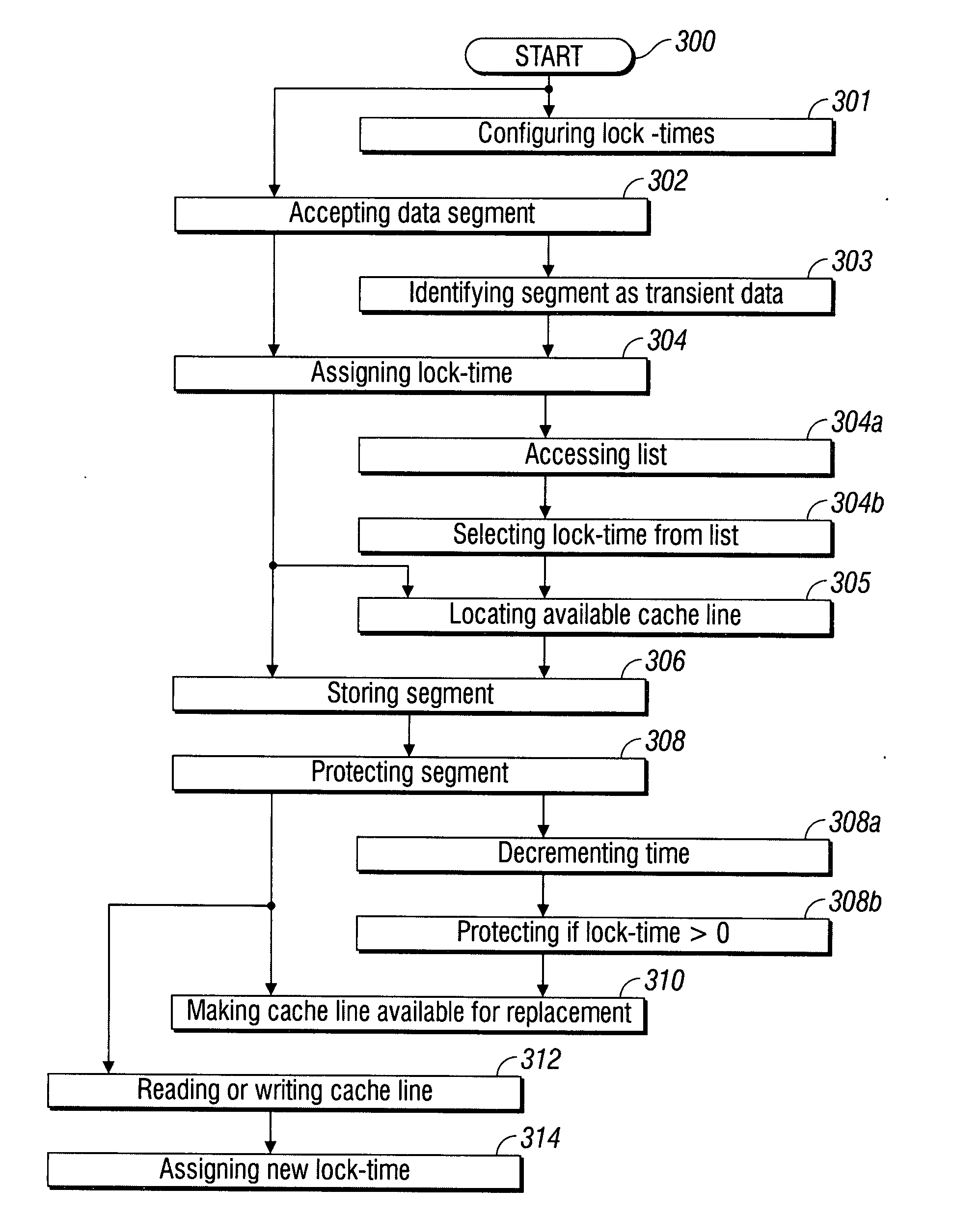
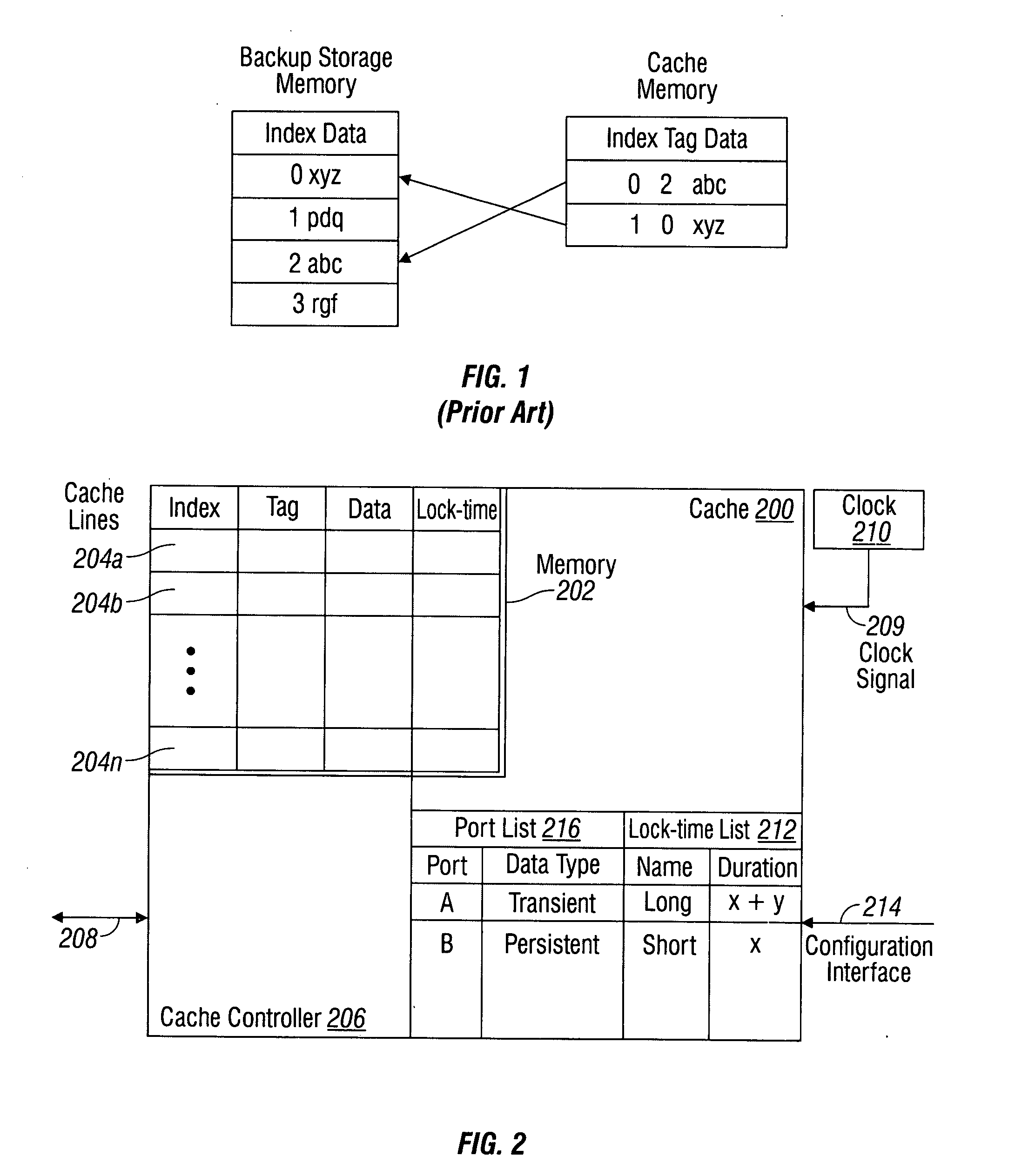
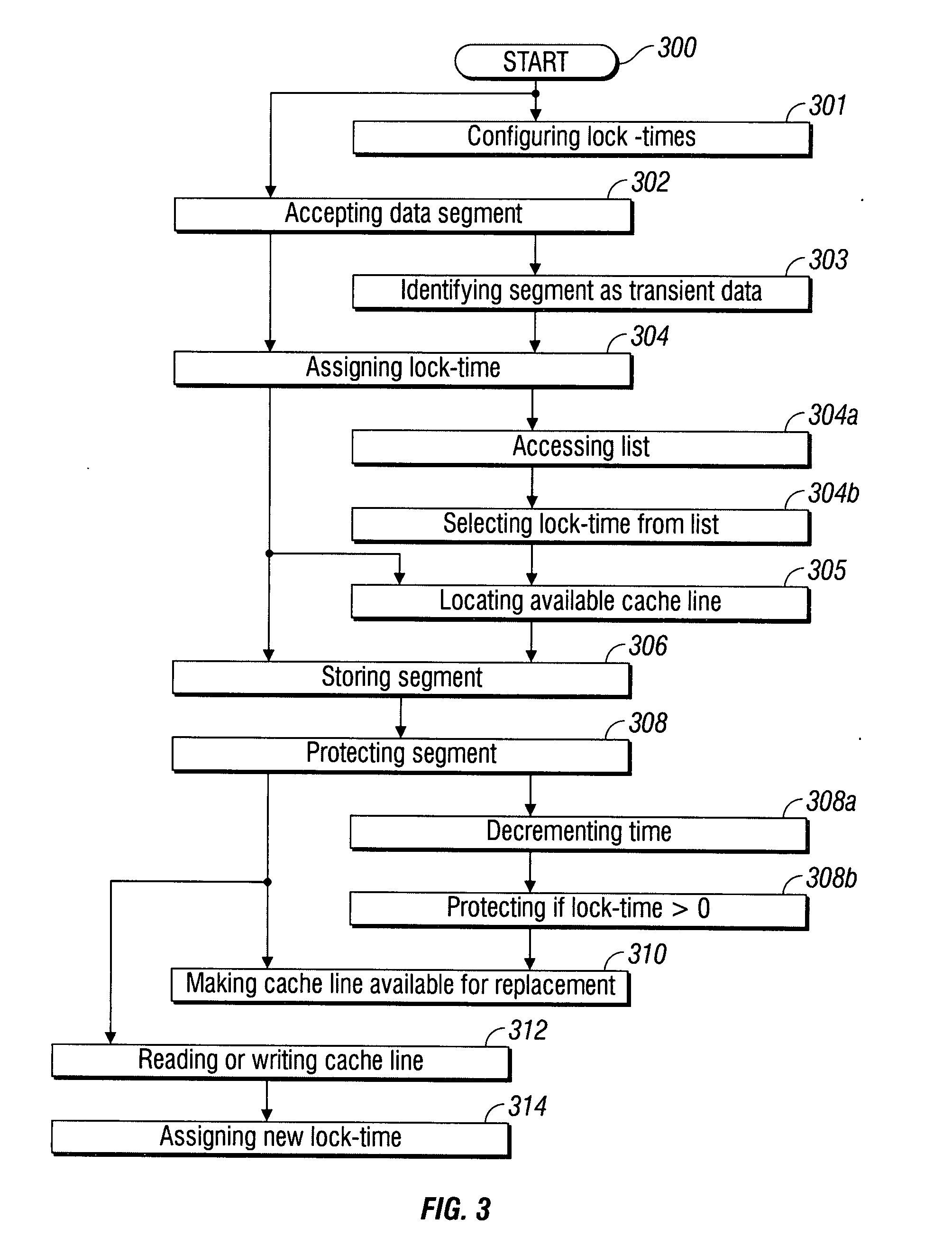
[0025]A time-based cache control mechanism is provided for the processing of transient or time sensitive data, for example, in network or digital signal processing applications. The cache control mechanism optimizes performance (cache and backing store efficiency), simplifies cache management, and protects against mismanagement. These benefits are achieved through combining a minimum guaranteed time in cache, if cache store is obtained, and replacement mechanisms to backing store, once the minimum guaranteed time elapses. New data can be marked cacheable without the knowledge of processor congestion. During periods of congestion, the time-based caching mechanism prevents excessive thrashing of the cache store as well as autonomously making “old” cache lines available for replacement, effectively removing the lock for valid lines which have exceeded their expected “time to live” period.

Problems solved by technology

Typically, the original data is expensive to fetch, due to a slow memory access time, or to compute, relative to the cost of reading the cache.
Alternately, when the cache is consulted and found not to contain a segment with the desired tag, a cache miss results.
If the cache has limited storage, it may have to eject some entries to make room for other entries.
While this system works well for larger amounts of data, long latencies, and slow throughputs, such as experienced with a hard drive and the Internet, it's not efficient to use these algorithms for cached main memory (RAM).
The data in the backing store may be changed by entities other than the cache, in which case the copy in the cache may become out-of-date or stale.
Alternatively, when the client updates the data in the cache, copies of that data in other caches will become stale.
Write-through operations are common when operating over unreliable networks (like an Ethernet LAN), because of the enormous complexity of the coherency protocol required between multiple write-back caches when communication is unreliable.
This large block of data may be necessary for interacting with a storage device that requires large blocks of data, or when data must be delivered in a different order than that in which it is produced, or when the delivery of small blocks is inefficient.
This algorithm requires keeping track of what was used when, which is expensive if one wants to make sure the algorithm always discards the least recently used item.
This caching mechanism is used when access is unpredictable, and determining the least most recently used section of the cache system is a complex operation.
Since it is impossible to predict how far in the future information will be needed, this algorithm is not conventionally implemented in hardware.
However, these replacement algorithms are not necessarily efficient for transient data.
The management of these on-chip resources can be complicated with the sizing of on-chip storage.
It is difficult to determine and map the different addresses required between the on-chip and off-chip stores.
However, the source (e.g., a line interface) may not be a processor and, hence, have no visibility into the processor congestion (work queue buildup).
The locking of cache lines in times of processor congestion can result in the number of locked lines increasing to the point where the overall cache efficiency degrades.

Method used


Image

  • Time-based cache control
  • Time-based cache control
  • Time-based cache control

Examples


Embodiment Construction

[0032]Various embodiments are now described with reference to the drawings. In the following description, for purposes of explanation, numerous specific details are set forth in order to provide a thorough understanding of one or more aspects. It may be evident, however, that such embodiment(s) may be practiced without these specific details. In other instances, well-known structures and devices are shown in block diagram form in order to facilitate describing these embodiments.

[0033]As used in this application, the terms “processor”, “processing device”, “component,”“module,”“system,” and the like are intended to refer to a computer-related entity, either hardware, firmware, a combination of hardware and software, software, or software in execution. For example, a component may be, but is not limited to being, a process running on a processor, generation, a processor, an object, an executable, a thread of execution, a program, and / or a computer. By way of illustration, both an appl...


PUM


Abstract

A time-based system and method are provided for controlling the management of cache memory. The method accepts a segment of data, and assigns a cache lock-time with a time duration to the segment. If a cache line is available, the segment is stored (in cache). The method protects the segment stored in the cache line from replacement until the expiration of the lock-time. Upon the expiration of the lock-time, the cache line is automatically made available for replacement. An available cache line is located by determining that the cache line is empty, or by determining that the cache line is available for a replacement segment. In one aspect, the cache lock-time is assigned to the segment by accessing a list with a plurality of lock-times having a corresponding plurality of time duration, and selecting from the list. In another aspect, the lock-time durations are configurable by the user.

Description

BACKGROUND OF THE INVENTION[0001]1. Field of the Invention[0002]This invention generally relates to digital memory devices and, more particularly, to a system and method for using a time-based process to control the replacement of data in a cache memory.[0003]2. Description of the Related Art[0004]Small CPU-related memories can be made to perform faster than larger main memories. Most CPUs use one or more caches, and modern general-purpose CPUs inside personal computers may have as many as half a dozen, each specialized to a different part of the problem of executing programs.[0005]A cache is a temporary collection of digital data duplicating original values stored elsewhere. Typically, the original data is expensive to fetch, due to a slow memory access time, or to compute, relative to the cost of reading the cache. Thus, cache is a temporary storage area where frequently accessed data can be stored for rapid access. Once the data is stored in the cache, the cached copy can be quic...

Claims


Application Information

Patent Timeline
IPC IPC(8): G06F12/00
CPCG06F12/126
Inventor FAIRHURST, MARK
Owner APPLIED MICRO CIRCUITS CORPORATION
Learn More