Light emitting diode illumination system

Active Publication Date: 2009-02-12
LUMENCOR
View PDF8 Cites 49 Cited by
  • Summary
  • Abstract
  • Description
  • Claims
  • Application Information

AI Technical Summary

Benefits of technology

[0009]The amount of white light produced can be increased by increasing the current density to the LED up to the point where the output of the LED rolls over and no longer increases with increasing current. The brightness of any LED made by in this general configuration is fundamentally limited by the internal and external quantum efficiency of the LED die, the quantum efficiency of the luminescent material, the amount of scattering by the particles, the thermal quenching properties of the die, and the die junction temperature. In contrast, the present invention is not limited by the current density of the LED as the length of the rod material could be increased to increase the number of excitation LED die and thereby increasing the output. For example, a high performance LED die with a 1 mm square area coated with a high performance phosphor can produce approximately 200 Lumens with a h

Problems solved by technology

The problems associated with these lamp technologies, however, include poor luminous efficacy thereby requiring high power and associated means of cooling, short lifetime, high voltage operation (typically kilovolts required to turn them on), high cost, and use of mercury which is becoming an environmental hazard and is in the process of undergoing regulations in numerous countries throughout the world.
To date no LED based endoscopic illumination system commercially exists that equals or exceeds the luminous intensity of the compact xenon arc lamp systems.
While blue and red LED modules can be produced t

Method used


Image

  • Light emitting diode illumination system
  • Light emitting diode illumination system
  • Light emitting diode illumination system

Examples


embodiment 80

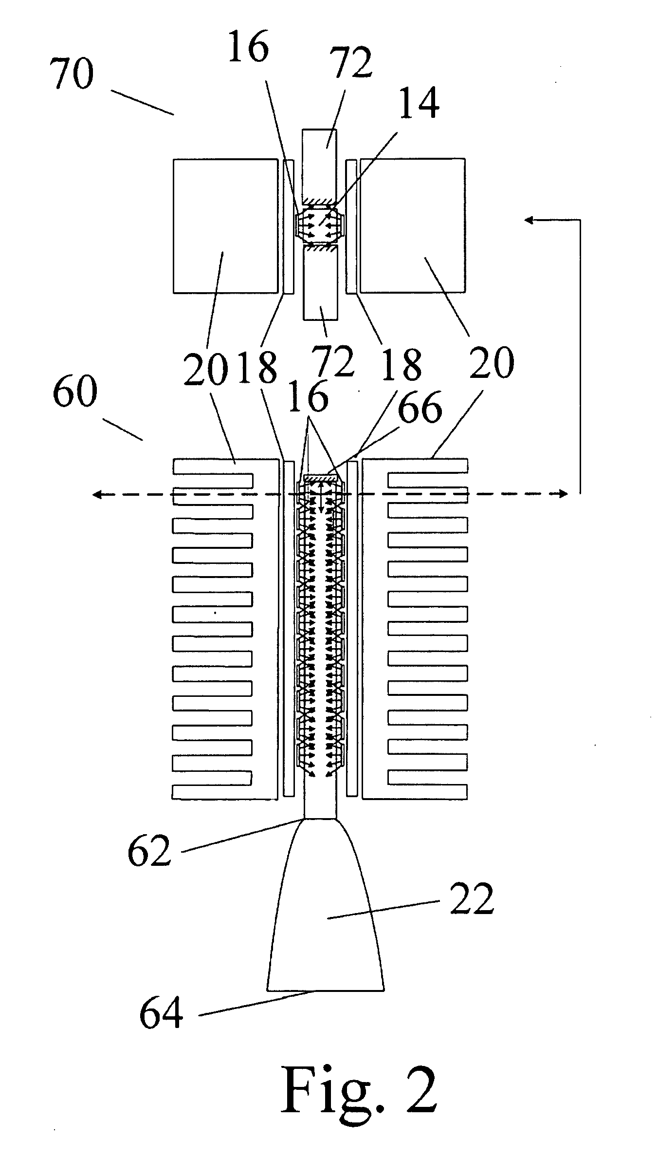
[0029]FIG. 3 shows an alternative embodiment 80 of the mirror elements 66 of FIG. 2 comprised of modified mirror elements 82 containing the addition of small holes 84 through which high pressure air would cool rod 14 by high pressure air impingement. The holes would be sufficiently small as to minimally affect the mirrored surface area of mirrors 82. High pressure air impingement has several times the film coefficient and thus heat transfer as compared to standard convected low pressure air. The effect of the slight increase in the index of refraction of the medium surrounding rod 14 on TIR would be minimal. If direct contact cooling fluid was used without the sides of the rod being reflective, the higher than air index of refraction of the fluid would result in more loss out through the sides due to the decreased TIR internal angle, thereby reducing overall LED module efficiency. The reason it may be important to provide a means of removing heat build up from the rod is that there ...

embodiment 120

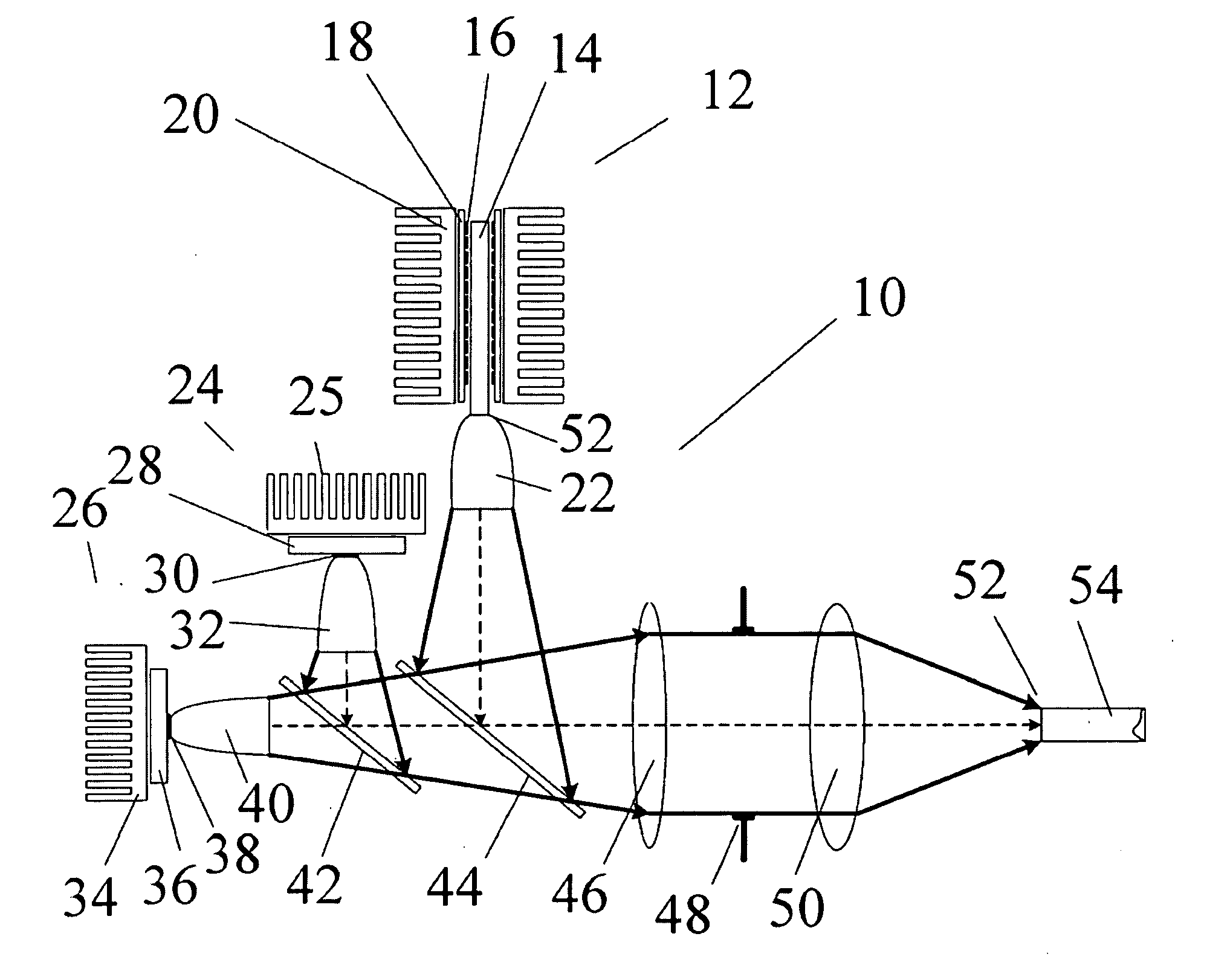
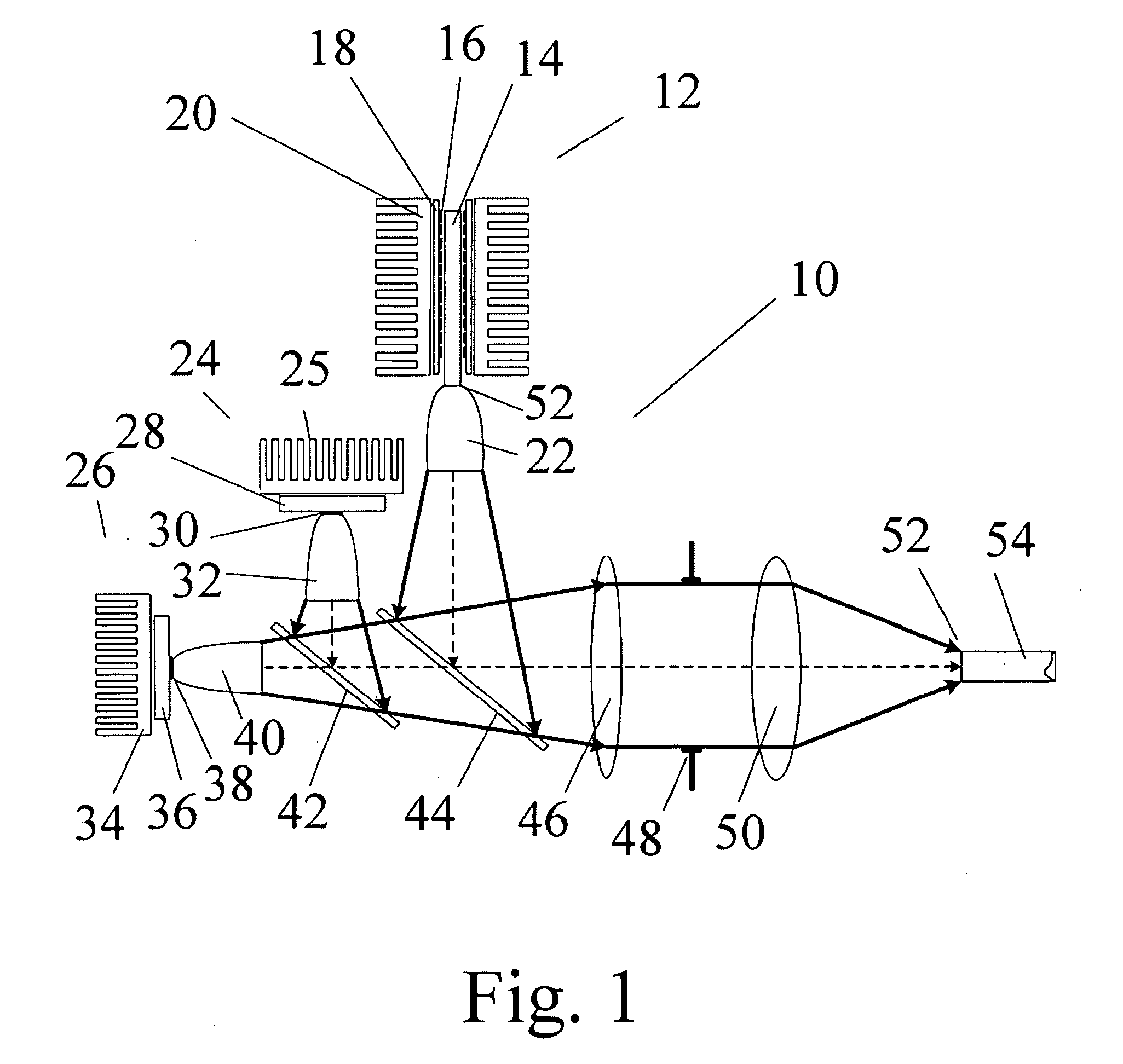
[0030]FIG. 4 shows an alternative embodiment 120 of LED module 12 of FIG. 1 where two modules 12 have been positioned in sequence to form a single multi-spectrum source. For example rod 122 of 120 could be made of a luminescent material with properties similar to those described for rod 14 for which the excitation band is within the long wavelength ultraviolet spectrum in the region of 240 nm to 420 nm. The high transmission region of the material would be in wavelengths longer than 420 nm and its luminescence could be in the blue to blue-green spectral region. Likewise rod 124 could have similar absorption properties but comprise luminescence in the green to red region of the spectrum. Both rods 122 and 124 would be characterized by high transmission in the spectral region containing wavelengths longer that 420 nm.

[0031]The mirror 66 would act to reflect any light transmitted in the direction opposite output coupler 22 back toward 22. In this way, LED light module 120 could contain...


PUM


Abstract

In various embodiments of the invention, a unique construction for Light Emitting Diodes (LEDs) with at least one luminescent rod and extracting optical elements used to generate a variety of high brightness light sources with different emission spectra. In an embodiment of the invention, forced air cooling is used to cool the luminescent rod. In an embodiment of the invention, totally internal reflected light can be redirected outward and refocused. In another embodiment of the invention, light emitted by the luminescent rod is out-coupled for use in a variety of applications.

Description

PRIORITY CLAIM[0001]This application claims priority to: (1) U.S. Provisional Patent Application Ser. No: 60 / 954,140, entitled: “LIGHT EMITTING DIODE ILLUMINATION SYSTEM”, inventor: Thomas Brukilacchio, filed Aug. 6, 2007, which application is incorporated herein by reference in its entirety.CROSS REFERENCE TO RELATED APPLICATIONS[0002]This application is related to the following application, which was filed of even date herewith:[0003]“LIGHT EMITTING DIODE ILLUMINATION SYSTEM” by Thomas Brukilacchio and Arlie Connor, Attorney Docket No. LUMEN-01020US0 SRM / AGC.FIELD OF THE INVENTION[0004]This invention, in general, relates to high brightness illumination sources and more particularly to the use of light emitting diodes (LEDs) as a source of illumination for medical endoscopy.BACKGROUND OF THE INVENTION[0005]There is a significant need for high brightness broad band illumination sources to provide optical fiber coupled illumination for surgical endoscopy and other applications where ...

Claims


Application Information

Patent Timeline
IPC IPC(8): G01N21/00F21V9/16
CPCA61B1/0653A61B1/0684A61N2005/005A61N2005/0652F21Y2101/02F21Y2105/00F21Y2113/00G01N2021/6419G01N2021/6482G01N2201/0627G02B6/0006G02B23/2469G02B27/0994G02B27/1006G02B27/143G02B27/145F21V13/02G01N21/64F21K9/52F21K9/56A61B1/00163A61B1/0669A61N5/062F21Y2115/10F21Y2115/30F21V9/30F21V13/08F21V5/008F21V13/14F21K9/60F21K9/61F21Y2113/13F21V29/70F21V13/04F21W2131/205F21W2131/40F21V29/60F21V7/0066F21K9/64
Inventor BRUKILACCHIO, THOMAS J.
Owner LUMENCOR
Why Eureka
Try Eureka