Method of Manufacturing and Installing a Ceramic Dental Implant with an Aesthetic Implant Abutment

a technology of ceramic dental implants and aesthetics, which is applied in the direction of dental prosthesis, boring tools, teeth capping, etc., can solve the problems of difficulty in deciding on the drill axis of the implant, the standard method of preparing the dental restorative system, and the difficulty of the oral surgeon in deciding on the drill axis for the implant, etc., to achieve the optimal loading of the implant and execute the effect of eas

Inactive Publication Date: 2009-02-12
ORATIO
View PDF7 Cites 185 Cited by
  • Summary
  • Abstract
  • Description
  • Claims
  • Application Information

AI Technical Summary

Benefits of technology

[0065]The primary advantage of the invention is that the oral surgeon may select the optimum position for a dental implant using the three-dimensional computer graphics model of the jawbone including the implant jaw and the position of the opposing teeth. The method allows the surgeon to interactively select an optimal position for a drill hole to be made in the jawbone in accordance with the optimal position for the dental implant. The optimal drill hole position not only relates to the coordinates of the planned drill hole on the jawbone, but also on the orientation of the drill hole (drill hole axis) within the jaw. Upon installation of the implant in the jaw, the implant will take the orientation of the drill hole.
[0066]Next, the selection of the drill hole position using the computer graphics model is transmitted to a centralized production facility where a drill guide is manufactured by a stereo lithography manufacturing method (SLA).
[0067]While the model is three-dimensional, it may be convenient for the purposes of selecting the drill hole axis to use a two-dimensional representation of the jawbone and the opposing teeth, the two-dimensional view being displayed with a user controlled angle. Preferably, the dental surgeon will select the position for each implant drill hole, not only to position each implant in the optimum location within the jawbone, but also to result in a position that is optimal in the loading of the implants during use for example, chewing. Therefore, it is preferred to display, in addition to the three-dimensional computer graphics model of the jawbone, the opposite teeth in the proper spatial relationship with respect to the jawbone. This requires im

Problems solved by technology

Standard methods for preparing dental restorative systems require considerable time, labor, and expense.
Accurate placement within the jawbone of the implants is a difficult task.
In the prior art, the oral surgeon typically has difficulty deciding on a drill axis for the implants since the ideal position for the implants should be decided with knowledge of the jawbone structure into which the implant is to be inserted, knowledge of the position within the jawbone structure of the nerve tissue, the gum surface and the required position and dimensions of the false teeth or dentures to be supported by the dental implant.
The imperfections may relate to a lack of ideal support, an unfavorable angulation of an implant causing a weakness in the implant which may cause failure over time, or a visually perceptible defect in the appearance of the prosthesis.
The procedure for manufacturing dental implant superstructures as known from the art is time-consuming and sometimes results in imperfect structures or defects in the visual appearance of the dentures to

Method used


Image

  • Method of Manufacturing and Installing a Ceramic Dental Implant with an Aesthetic Implant Abutment
  • Method of Manufacturing and Installing a Ceramic Dental Implant with an Aesthetic Implant Abutment
  • Method of Manufacturing and Installing a Ceramic Dental Implant with an Aesthetic Implant Abutment

Examples


example 1

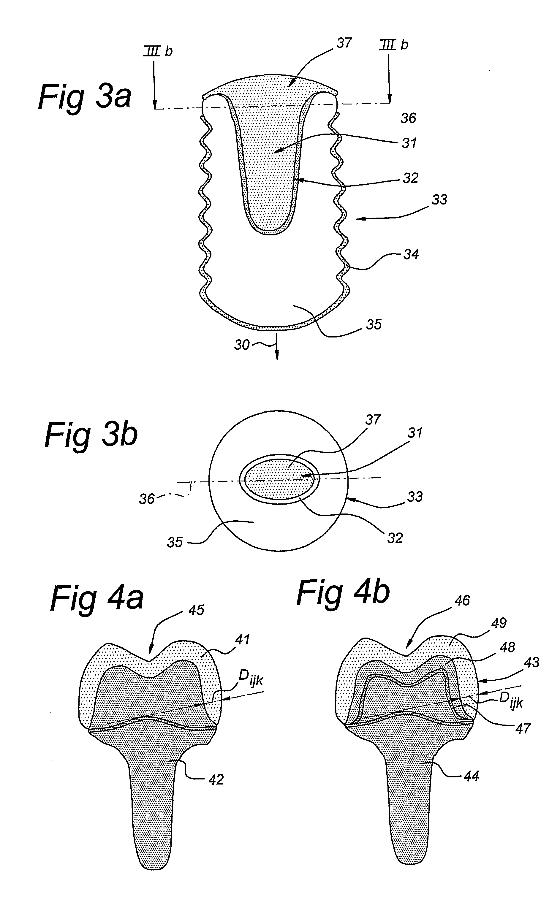
[0261]Zirconia Compound “PXA100P” of Tosoh Corporation, Tokyo, Japan is pre-mixed with 1000 ppm Fe3+ for pigmentation to a tooth like shade. The mixture has a melting / injection temperature of 190-220° C. and is injection molded in a form which has a retractable part that forms an elliptical female recess to receive the male extension of the abutment core. The wax binder is removed by heating slowly to a temperature of about 450° C. and annealing at that temperature for about 3 hours in air. The implant is pre-sintered at about 800° C. for about 1 hour in air until neck forming has taken place to obtain a porous structure that is stable enough to be handled. The pre-sintered implant is fixed in a precisely vertical position in a dipping machine and submerged in a slurry consisting of a mixture of hydroxyapatite crystals and zirconia in a carrier liquid, containing dispersing agents and binders as four examples show in table 1.

[0262]Hydroxyapatite crystals of 20-50 nm diameter (Alfa-A...

example 2

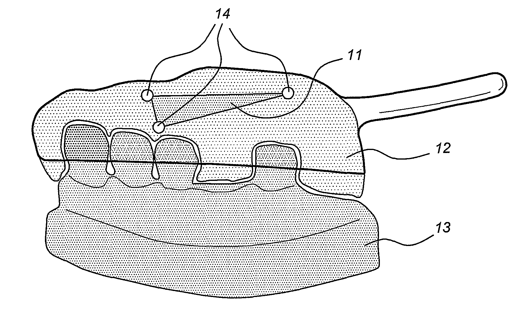
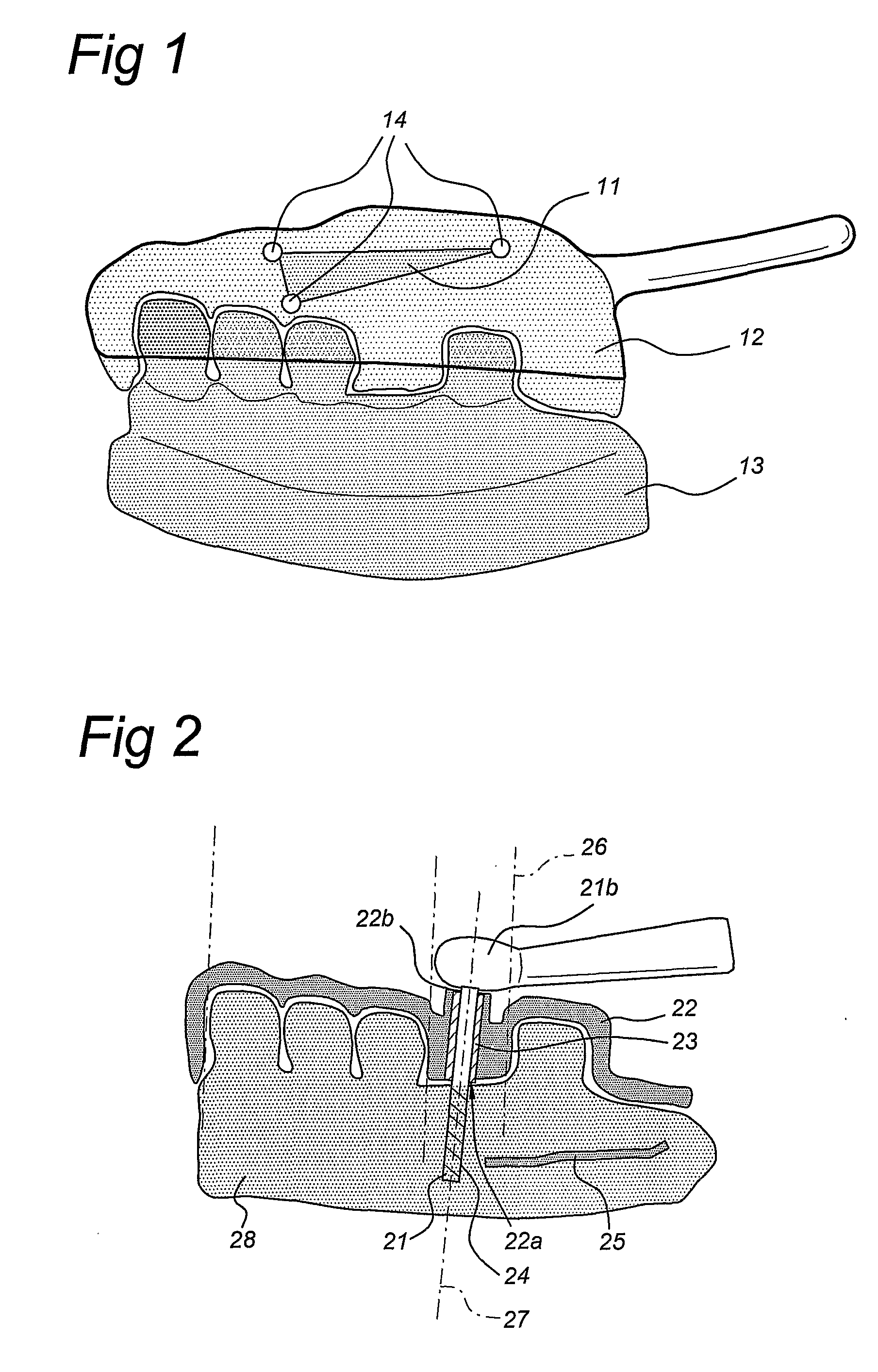
[0265]An impression is made of the arch to be implanted with a U-form non-opaque tray, filled with silicone, with three zirconia spheres attached in such a way that they are visible when the impression tray is in position. The silicone negative is poured in gypsum. The gypsum cast of the gypsum model is marked where the drill guide should end with black / white contrast for unambiguous scanning of the support area of the guide. Then a registration bite impression is made, while the patient bites in central occlusion. The patient is then scanned by X-ray Cone Beam Computed Tomography with the DVT 9000 of QR s.r.l., Verona (It). During scanning the impression tray with reference spheres is placed in the proper position in the patient mouth. After the CT scan and processing of the measurements, the operator checks whether all three reference spheres are visible in the X-ray image in three views to allow identification.

[0266]The next step in the automated fabrication of a drill guide and ...

example 3

[0282]As an example: For the abutment core with a CIE-lab color: L*=73.6, a*=4.2, b*=19.4, a cover layer of with CIE-lab color: L*=70.6, a*=5.3, b*=21.2 with a thickness of 0.75 mm results at the outer surface in a CIE-lab color: L*=71.1, a*=5.1, b*=22.1, which corresponds with a traditionally measured VITA® lumen shade guide (Vita Zahnfabrik, DE) of “A3” (see also: Dozic, A; Kleverlaan, C J; Meegdes, M; vanderZel, J M; Feilzer A J, The influence of porcelain layer thickness on the final shade of ceramic restorations, J Prosth Dent 2003; 90:563-70).


PUM

PropertyMeasurementUnit
Temperatureaaaaaaaaaa

Abstract

The present invention relates to a method for manufacturing a tooth prosthesis, for insertion in a jawbone, including an implant and an abutment on top of the implant. The method includes: defining a shape of the prosthesis and its location in the jawbone by using first data from a first CT scan image of the jawbone and second data from a second image of a gypsum cast, correlating first and second data by extracting from the first data first position reference data of a first reference in the first image, and from the second data second position reference data of a second reference in the second image, the second reference being identical to the first reference; performing a geometric transformation on the second data and/or the first data to have a coincidence of the second image with the first image and to combine the first and second data into composite scan data.

Description

FIELD OF THE INVENTION[0001]The invention relates to a method for manufacturing a prosthesis for replacing at least one tooth, the prosthesis being arranged for insertion in a patient's jawbone, the prosthesis comprising an implant and an abutment in accordance with the preamble of claim 1. Also, the invention relates to a method for manufacturing a drill guide for use with the manufacturing of the prosthesis. Moreover, the present invention relates to a prosthesis comprising an implant and an abutment. Furthermore, the present invention relates to a drill guide for use in a patient's jaw bone without the need for a flapping operation. Also, the present invention relates to an impression tray for taking an impression of a denture of a patient. The present invention also relates to a computer system and a computer program product for manufacturing a prosthesis for replacing at least one tooth.BACKGROUND OF THE INVENTION[0002]Dental restorative systems seek to provide cosmetic and fun...

Claims


Application Information

Patent Timeline
IPC IPC(8): A61C13/20A61C8/00A61C13/225A61C9/00G06K9/00A61K6/90
CPCA61C1/084A61C8/0012A61C8/0013A61C8/005A61C8/0069A61C13/0003A61C9/0053A61C13/0019A61C13/0022A61C13/206G01J3/46G01J3/463G01J3/508A61C13/0004B33Y80/00A61C13/00A61C13/08A61C8/00
Inventor VAN DER ZEL, JOSEPH MARIA
Owner ORATIO
Why Eureka
Try Eureka