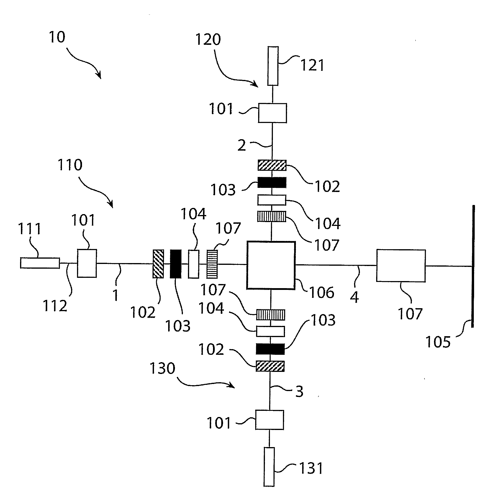
[0010]The invention is based on an insight that by use of a diffuser arranged on the light outgoing side of an LCD panel in an image projection system, which comprises a laser based illumination source, the quality of the projected image can be improved. Advantageously, the diffuser broadens small and well focused modulated
laser beams, such that the projected image is provided with a more homogenous intensity distribution and imperfections in the
optical path becomes less visible. In other words, the general idea is to broaden the beam after it has been modulated, but before it passes the
projection optics. This gives an easy modulation, as the beam is confined at the modulation, as well as reduces problems related to large field of depth.
[0016]One
advantage associated with the three aspects mentioned above is that they provide a better perceived quality of the projected image, due to e.g. that imperfections in the optical system is less visible and that there is a greater homogeneity in the projected image, without the loss of any image information. The imperfections in the projected image are made less visible by a
diffusion of the modulated light. The diffuser or etendue transforming element diffusing the light is further arranged such that each pixel in the image is clearly visible.
[0017]Advantageously, the etendue transforming element is arranged such that the etendue transformed illumination beam has a substantially uniform far
field intensity distribution, or
angular distribution. This can be achieved with e.g. a diffractive beam shaper element. In other words, the etendue transformed illumination beam preferably has a top hat like scattering distribution and even more preferably a rectangular
angular distribution. This can be achieved with e.g. a beam shaper element. In other words, the projected image can be improved and made more homogenous without the loss of any substantial amount of light. Further, the etendue transforming element is advantageously a holographic diffuser, as these can be tailor made to meet specific demands on optical properties in a cost effective way.
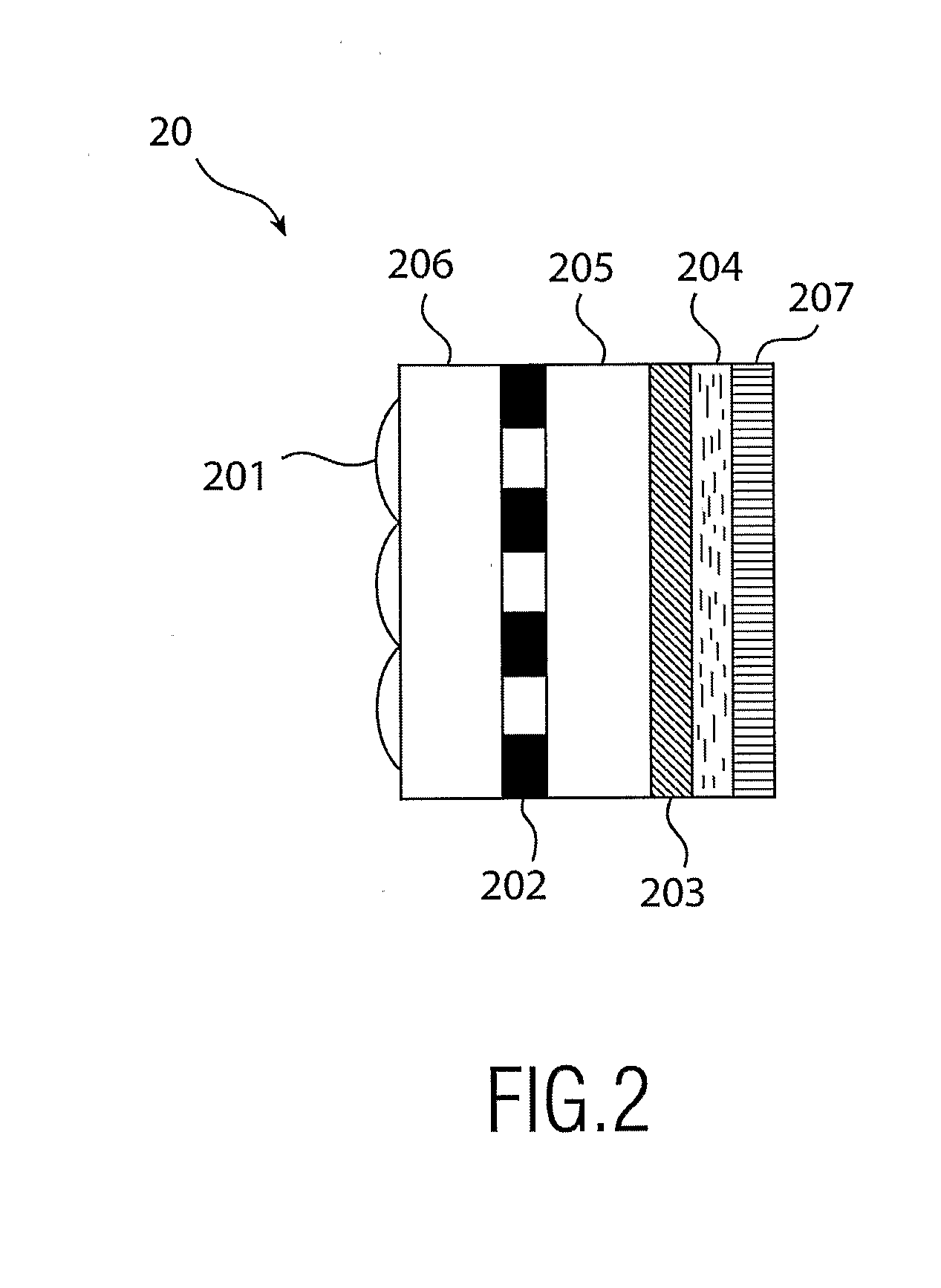
[0019]The
visibility of speckles can also be reduced by providing a
liquid crystal layer on an etendue transforming element, having a rough diffusing surface. The
liquid crystal layer is electro-optically modulated, such that the
transmitted light is switched between a diffused and less or not diffused state. Such devices are known in the art. For example, a switchable
liquid crystal layer is provided on the rough down
stream facing side of a
polarization dependent diffuser. The liquid
crystal layer can be switched between an active and a passive state by the application or removal of an
electric field, which rotates the crystals in the LC material, which rotation affects the
refractive index of the liquid
crystal material. In the passive state the
refractive index of the liquid
crystal layer is arranged such that the light is simply transmitted through the switchable layer, without being substantially affected. In the
active state, the
refractive index of the liquid crystal layer corresponds to that of the etendue transforming element. Hence, the broadening of the light is eliminated or reduced, because the liquid crystal layer is arranged on the rough diffusing layer of the diffuser and has a matching refractive index. The switchable etendue transforming element is preferable combined with an ordinary or non-switchable etendue transforming element, to avoid a high in line transmission in the
active state. This electro-optical modulation has the
advantage that no
moving parts are used.
[0020]Advantageously, a micro-
lens array is arranged on the light incoming side of the image panel, such that the illumination beam is better focused onto the respective pixels in the image panel. This enables a use of an image panel having smaller pixels, i.e. the center to center distance between two pixels can be made smaller without the loss of any light. In other words, a geometrically smaller image panel can be used.
[0022]The
gist of the invention is to expand the beam after is has been modulated, and keep the low etendue (confined) beam for ease of modulation. Expansion of the beam before the projection
optics reduces the focal depth and thus makes the system less sensitive to imperfections in the projections
optics.

