Microreactor

Inactive Publication Date: 2009-02-19
DAI NIPPON PRINTING CO LTD
View PDF5 Cites 7 Cited by
  • Summary
  • Abstract
  • Description
  • Claims
  • Application Information

AI Technical Summary

Benefits of technology

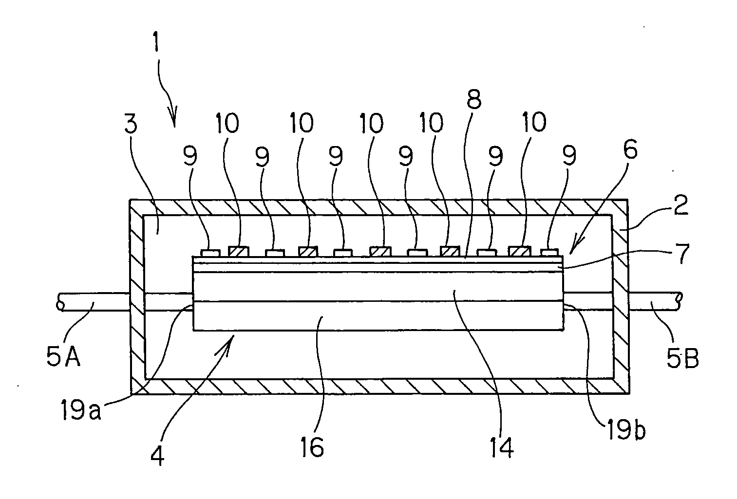
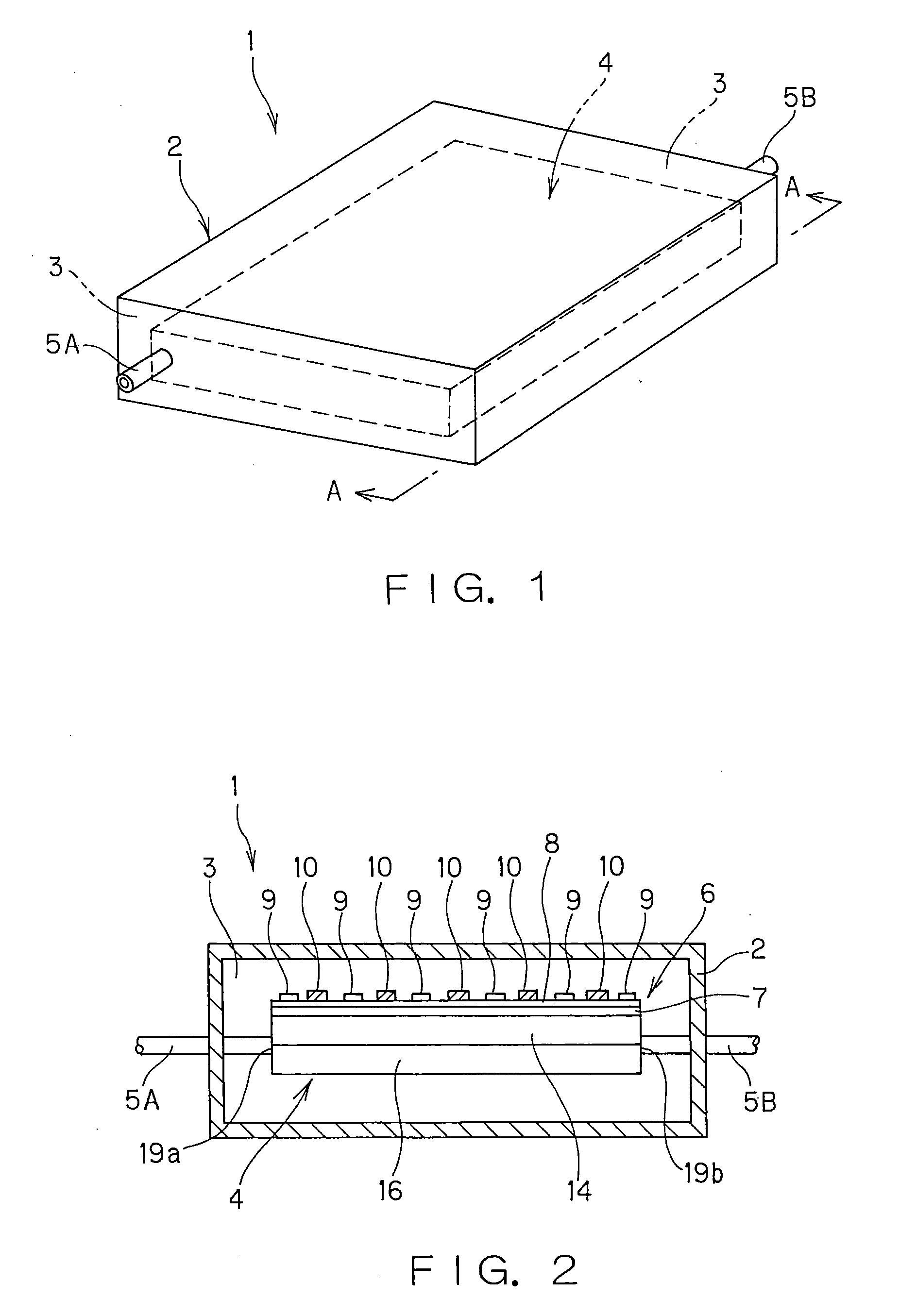
[0015]According to the invention as recited above, the microreactor proper is positioned within the vacuum-tight cavity in the vacuum casing, and the vacuum-tight cavity is maintained by the getter material layer of the getter heat-generation substrate. Thus, even when the micro-reactor proper is placed in a high-temperature state, the vacuum-tight cavity effectively cuts off the conduction of heat from the microreactor proper to outside. Besides, the heat insulation effect by that vacuum-tight cavity is much higher than could be achieved with the use of other heat insulator, making it possible to place the outer wall temperature of the microreactor (vacuum casing) at normal temperature to about 50° C. without rendering the vacuum casing bulky. It is thus possible to achieve a micro-reactor that, albeit being of small size, holds back influences of heat on outside and ma

Problems solved by technology

However, to locate a known heat insulator such as one formed of glass wool or ceramic material around the microreactor in the high temperature state thereby reducing the outer wall temperature of the insulator

Method used


Image

  • Microreactor
  • Microreactor
  • Microreactor

Examples


example 1

[0083]A 1-mm thick SUS316L substrate (25 mm×25 mm) was readied up for a metal substrate, and a photosensitive resist material (OFPR made by Tokyo Ohka Kogyo Co., Ltd.) was coated on each surface of SUS316L by dipping (at a post-drying thickness of 7 μm). Then, a photomask configured such that striped light block portions of 1,500 μm in width extending alternately 20 mm from the left and right sides at a pitch of 2,000 μm was located on the resist coating of the SUS316L substrate on the side to be provided with fine grooves. Besides, a photoresist material was likewise coated on a similar SUS316L substrate as mentioned above, followed by the location of a photomask on the resist coating of the SUS316L substrate on the side to be provided with fine grooves. This photo-mask was of plane symmetry about the first-mentioned photomask with respect to the SUS316L substrate plane.

[0084]Then, the resist coatings of the aforesaid one set of SUS316L substrates were exposed to light through the ...

example 2

[0103]Four 1-mm thick SUS316L substrates (25 mm×25 mm) were readied up as metal substrates. Both surfaces of these SUS316L substrates were coated by dipping with a photosensitive resist material (OFPR made by Tokyo Ohka Kogyo Co., Ltd.) (at a post-drying thickness of 7 μm). Then, a photomask having three rows of rectangular (6 mm×20 mm) light-block portions at a pitch of 7 mm was located on the resist coating on the surface of each SUS316L substrate to be grooved, while a photomask having three 4-mm diameter circular light-block portions at a pitch of 7 mm was located on the resist coating on the opposite surface of each SUS316L substrate. Then, the resist coatings were exposed to light via the photomasks, and developed with a sodium hydrogen carbonate solution, whereby there was a resist pattern formed, in which rectangular openings (of 6 mm×20 mm) were lined up on one surface of each USU316L substrate at a pitch of 7 mm in three rows, three 4-mm diameter circular openings were lin...


PUM

PropertyMeasurementUnit
Currentaaaaaaaaaa
Digital informationaaaaaaaaaa
Electric propertiesaaaaaaaaaa

Abstract

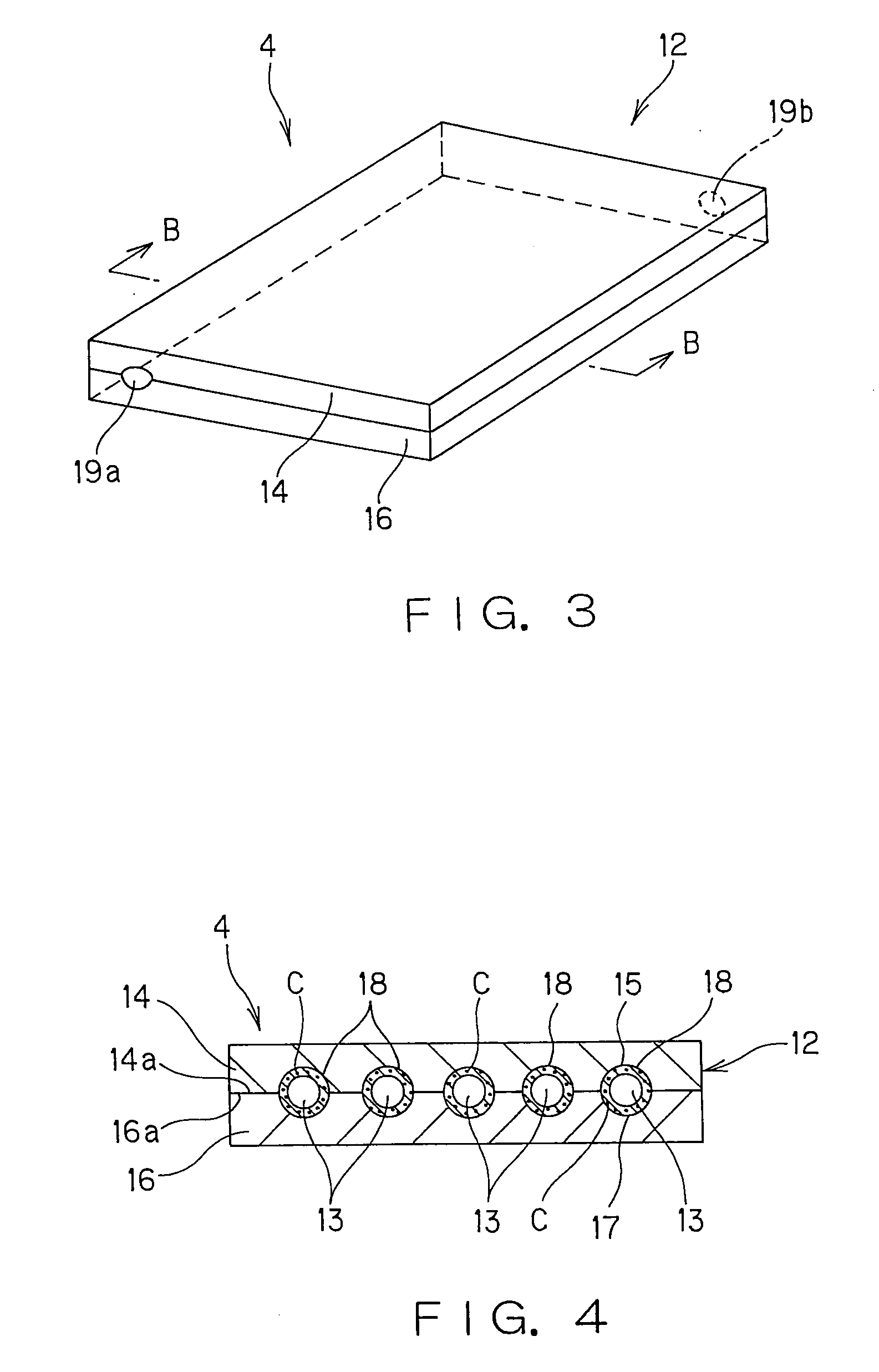
A microreactor (1) comprises a vacuum casing (2), a microreactor proper (4) located in a vacuum-tight cavity (3) in the vacuum casing (2), and a getter heat-generation substrate (6) positioned on at least one surface of the microreactor proper (4). The microreactor proper (4) has a feed inlet (19a) connected to outside the vacuum casing (2) by way of a feed supply pipe (5A) and a gas outlet (19b) connected to outside the vacuum casing (2) by way of a gas discharge pipe (5B). The getter heat-generation substrate (6) comprises a substrate (7), and a heat generator (9) and a getter material layer (10) that are located on the substrate (7) alternately in mutual non-contact fashion.

Description

ART FIELD[0001]The present invention relates generally to a microreactor, and more particularly to a microreactor adapted to keep the desired reactions going on by a carried catalyst.BACKGROUND ART[0002]So far, reactors harnessing catalysts have been used in various fields, and they are best designed depending on what purposes they are used for.[0003]On the other hand, use of hydrogen as fuel has recently attracted attention, partly because of no spewing of such global warming gas as carbon dioxide in terms of global environmental protection, and partly because of high energy efficiency. Fuel cells in particular have gained attention, partly because they can convert hydrogen direct into electric power, and partly because they are capable of high energy conversion efficiency in cogeneration systems making use of generated heat. The fuel cells have hitherto been used under more specific conditions: for space development, ocean development, etc., and they are now going as far as the de...

Claims


Application Information

Patent Timeline
IPC IPC(8): B01J19/00
CPCB01J19/0093Y02B90/18B01J37/0217B01J37/0225B01J37/0242B01J37/349B01J2219/00153B01J2219/00783B01J2219/00822B01J2219/00835B01J2219/0086B01J2219/00873C01B3/384C01B2203/0227C01B2203/066C01B2203/0805C01B2203/1064C01B2203/1076H01M8/0618H01M2250/30Y02E60/50B01J23/80Y02B90/10Y02P20/52B01J19/00B81B1/00H01M8/06
Inventor KIHARA, TAKESHIYAGI, HIROSHITAKEUCHI, AKIHIKO
Owner DAI NIPPON PRINTING CO LTD
Why Eureka
Try Eureka