
Real-time onsite internet communication with well manager for constant well optimization

a technology of internet communication and well manager, applied in the field of real-time onsite internet communication with well manager for constant well optimization, can solve the problems of simple clock timers not responding to actual well conditions, damage to drive units or downhole pumps, and lower well production efficiency

Active Publication Date: 2009-02-26
LUFKIN INDUSTRIES
View PDF58 Cites 96 Cited by
  • Summary
  • Abstract
  • Description
  • Claims
  • Application Information

AI Technical Summary

Benefits of technology

[0036]In an oil field of multiple wells, each rod pump has an individual and dedicated well manager with an integral web server that is independent of all others. This system eliminates the need for traditional SCADA systems.

Problems solved by technology

This “fluid pound” lowers well production efficiency and over time can cause damage to the drive unit or downhole pump, such as broken rods.
However, simple clock timers are not responsive to actual well conditions and do not detect actual pump-off conditions.
In addition to running a rod pump in a pumped-off state, other abnormal conditions of the pump operation reduce well production efficiency.
Common abnormal conditions include tubing movement, gas interference, an inoperative pump, the pump hitting up or down, a bent barrel, a sticking pump, a worn plunger or traveling valve, a worn standing valve, a worn or split barrel, fluid friction, and drag friction.
This method of pump diagnosis and troubleshooting is costly both in terms of labor costs and lost revenue from the well.
However, because the surface card is not always an accurate representation of the load and displacement of the downhole rod string, particularly for deep wells, more accurate well control is achieved by using a “downhole card,” i.e., a plot of load versus rod string displacement as measured at the downhole pump.
The measured data was retrieved by the costly process of pulling the rods and pump.
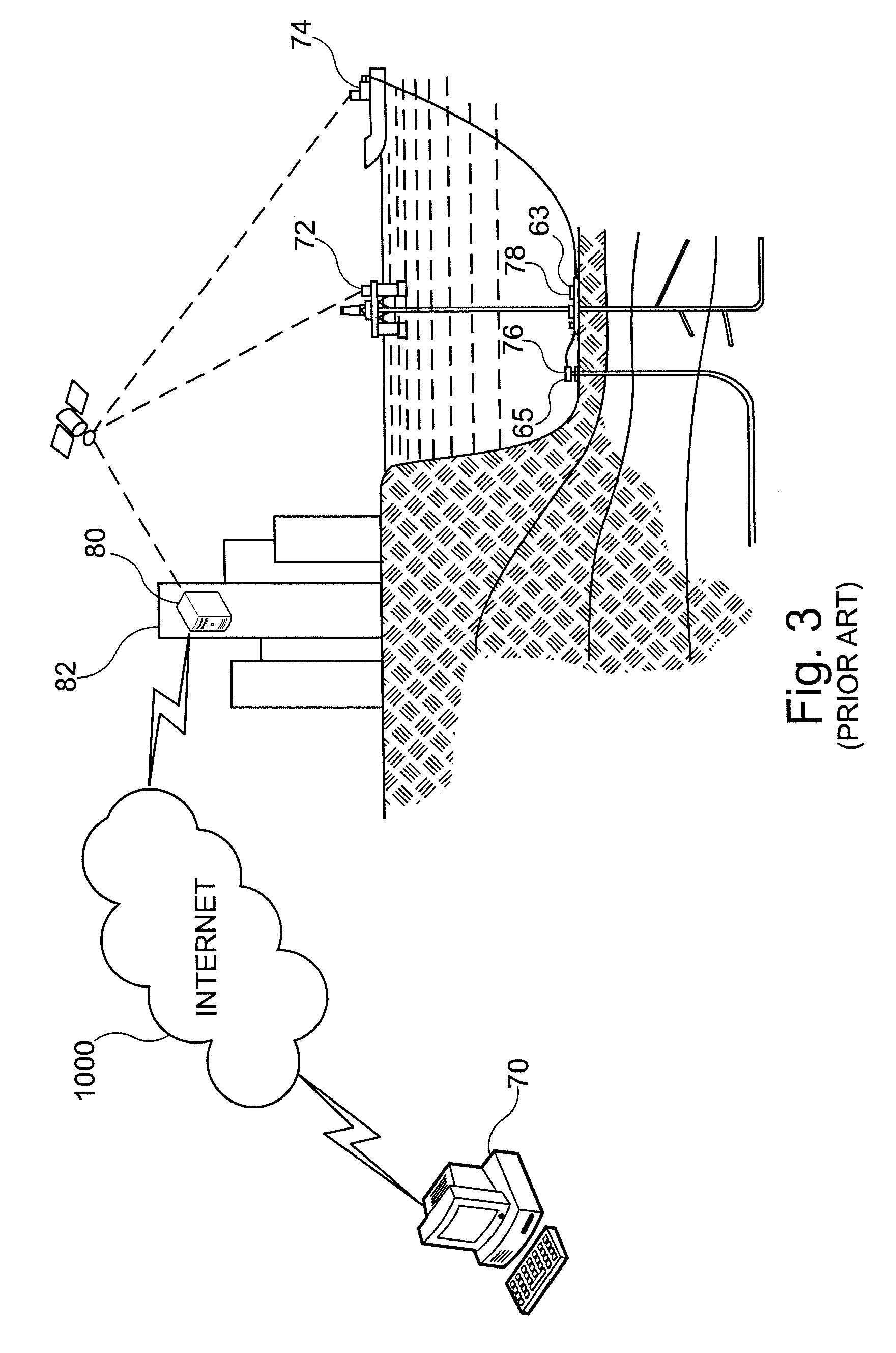
Because even today these measurements are not easily directly obtained, requiring a costly telemetry system to relay the data to the surface, methods have been developed to calculate the downhole dynagraph from the more easily obtained surface card.
For example, a decline in production rate can corroborate a mechanical problem indicated by a downhole card; the downhole pump may be worn or a tubing leak may have developed.
The decline may also be caused by a change in reservoir conditions in the drainage area of the well; the receptivity of an offset injection well may have diminished, which may have resulted in a producing pressure decline and a decrease in production rate.
However, the benefit of the well manager features is diminished when the operator must be present at the well site to see and analyze the well data.
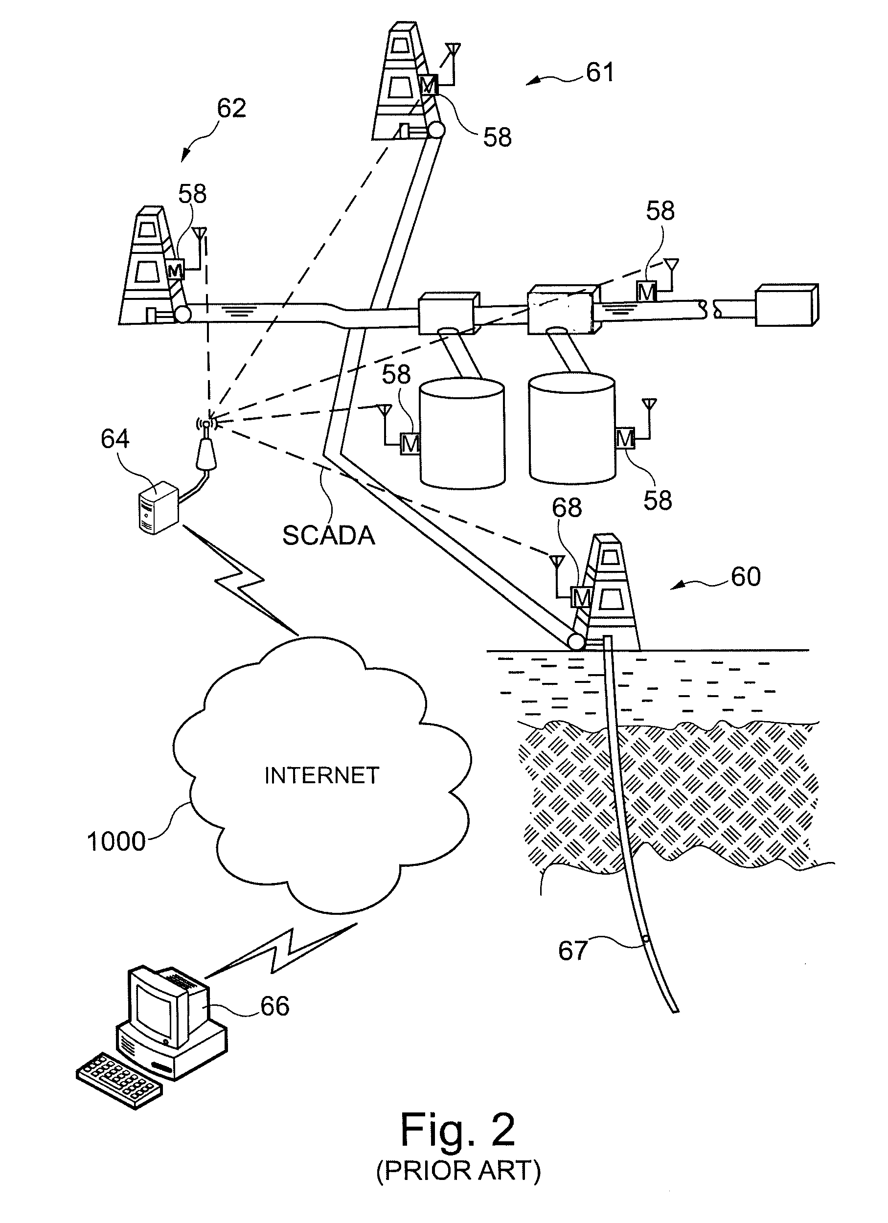
Furthermore, the SCADA system may be configured to send alarms, allowing problems to be timely announced.
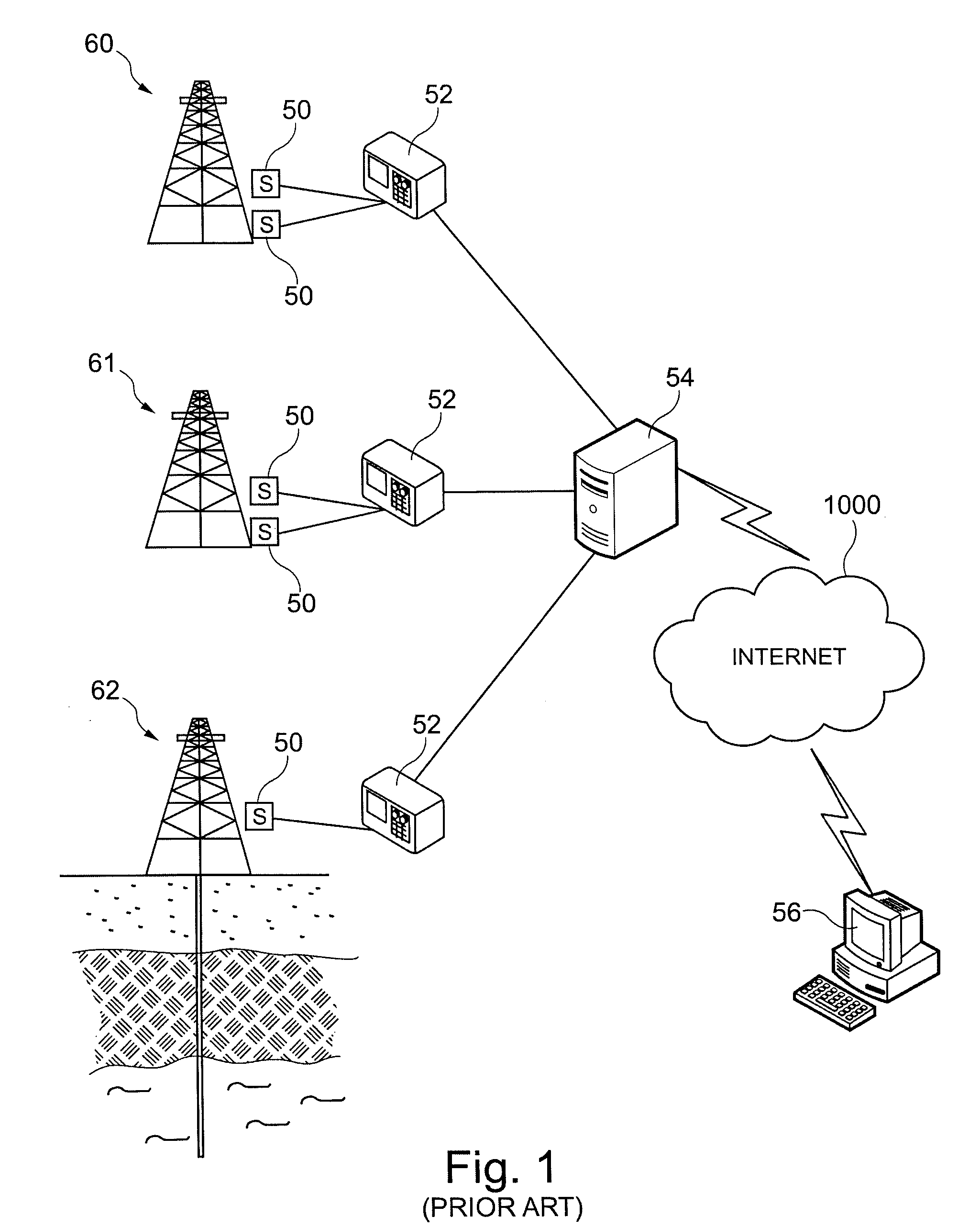
Although current SCADA systems provide some remote connectivity between a remote site and a number of well managers in an oil field, they generally employ expensive proprietary hardware and short-range RF radios of low bandwidth.
However, Bramlett's teaching is limited to using the internet to remotely display graphical surface and downhole cards; Bramlett does not disclose sending well production reports, statistics, pump diagnostics, alarms, alerts or other data from the well manager to remote users via the internet or receiving control data at the well manager from remote users over the internet.
Ramakrishnan does not disclose that the controllers are adapted to control rod pumps or that the controllers calculate downhole and surface cards or infer production.
Hill does not disclose controllers adapted to control rod pumps or to calculate downhole and surface cards.
Tubel does not disclose that the system is adapted to control rod pumps or to calculate downhole and surface cards.
Although each remote client computer has internet connectivity, they do not function as internet servers, and the data is not processed locally.

Method used


Image

  • Real-time onsite internet communication with well manager for constant well optimization
  • Real-time onsite internet communication with well manager for constant well optimization
  • Real-time onsite internet communication with well manager for constant well optimization

Examples


Embodiment Construction

[0023]A primary object of the invention is to provide a well manager for controlling a rod pump with constant and direct internet connectivity and the capability to act as a web server so that the well manager can host a remote user directly via the internet at any time from anywhere in the world to provide the remote operator unlimited access to critical operating data.

[0024]Another object of the invention is to provide a well manager that processes well data at the well site and requires little or no post-processing of collected data.

[0025]Another object of the invention is to eliminate the need for specialized and proprietary SCADA protocols and hardware connection methods such as direct serial communication, or other polling-style communication methods to provide data to a distant central location.

[0026]Another object of the invention is to provide a well manager unit that requires only standard commercial off-the-shelf computer technology.

[0027]Another object of the invention i...


PUM


Abstract

An apparatus and method for well control and monitoring including an independent web server computer integrated with a pump controller located at each well in an oil field. The well controller locally controls the well pump, processes well and pump data, generates surface and downhole cards, and communicates production reports, recommendations for production improvements, and production statistics to remote sites via the internet. The controller can be queried remotely to provide production reports, etc. Furthermore, the controller can initiate alerts via email, text messaging, or internet messaging, for example, during fault conditions.

Description

BACKGROUND OF THE INVENTION[0001]1. Field of the Invention[0002]This invention relates generally to methods and apparatus for remotely monitoring, controlling, and automating the operation of pumps for the production of hydrocarbons and dewatering, for example, and more specifically to a controller for rod pumps, progressing cavity pumps, injection well control, variable speed drives, well gas measurement, et cetera, for continuous optimization thereof.[0003]2. Description of the Prior Art[0004]Hydrocarbons are often produced from well bores by sucker rod pumps, reciprocating pumps driven from the surface by pumping units that move a polished rod up and down through a packing gland at a wellhead. The units may be of the predominant beam type or any other type that reciprocates the polished rod.[0005]Because the incremental cost of larger sucker rod pumps is usually less than the added value realized by producing oil from the wells at the highest possible rate, sucker rod pumping uni...

Claims


Application Information

Patent Timeline
IPC IPC(8): G06F19/00E21B47/00
CPCE21B47/00G05B23/0267G08B21/00G01V3/00G05B2219/13G05B2223/06
Inventor ROBERSON, ALAN L.DORADO, DONEIL M.PINNELL, DAVID L.OESTREICH, ERIC S.
Owner LUFKIN INDUSTRIES
Learn More