Linearized Swept Laser Source for Optical Coherence Analysis System

a laser source and optical coherence technology, applied in semiconductor lasers, material analysis, instruments, etc., can solve the problems of high speed tuning and maintaining long coherence length that is difficult to achieve in conventional tunable lasers, and the required cavity length is typically difficult to achieve with conventional external cavity semiconductor lasers. achieve the effect of high speed, high tuning speed, and long life of tunable lasers

Inactive Publication Date: 2009-03-05
AXSUN TECH
View PDF9 Cites 20 Cited by
  • Summary
  • Abstract
  • Description
  • Claims
  • Application Information

AI Technical Summary

Benefits of technology

[0008]Dwell time of a tunable laser at high tuning speed can be increased by using a short laser cavity length with a correspondingly small cavity roundtrip time. Such a short required cavity length, e.g. 10 to 30 millimeters (mm), is typically difficult to achieve with conventional external cavity semiconductor lasers. Using micro-electro-mechanical system (MEMS) tunable filters and optical micro-bench packaging allows such compact tunable lasers, however.
[0009]Furthermore, as the cavity length gets smaller, cavity mode spacing gets larger, so that fewer modes remain lasing under the narrow tunable filter spectral envelope, eventually leaving just a single lasing mode. Conventional thinking has assumed that a continuously tuned laser mode or a group of modes is required for OCT imaging. However, since OCT data is read at discrete time intervals anyway, a laser tuned over a discrete set of individual wavelengths should be also suitable for OCT imaging. Such a discretely tuned single mode laser can have a short laser cavity and thus capable of operating at very high speeds with dwell times sufficiently high for maintaining the long required dynamic coherence length.
[0010]The present invention concerns a wavelength tuned laser for an optical coherence analysis system. The laser hops between single discrete modes of the laser cavity. The laser can be tuned at very high scanning speeds while maintaining long coherence length. Further, laser frequency tuning with time can be linearized with a high utilization duty cycle.

Problems solved by technology

Simultaneous high speed tuning while maintaining long coherence length is difficult to achieve in conventional tunable lasers, such as conventional external cavity semiconductor tunable lasers.
Such a laser, however, is bulky, has complications related to using very long fiber, and has a number of other limitations.
Such a short required cavity length, e.g. 10 to 30 millimeters (mm), is typically difficult to achieve with conventional external cavity semiconductor lasers.

Method used


Image

  • Linearized Swept Laser Source for Optical Coherence Analysis System
  • Linearized Swept Laser Source for Optical Coherence Analysis System
  • Linearized Swept Laser Source for Optical Coherence Analysis System

Examples


first embodiment

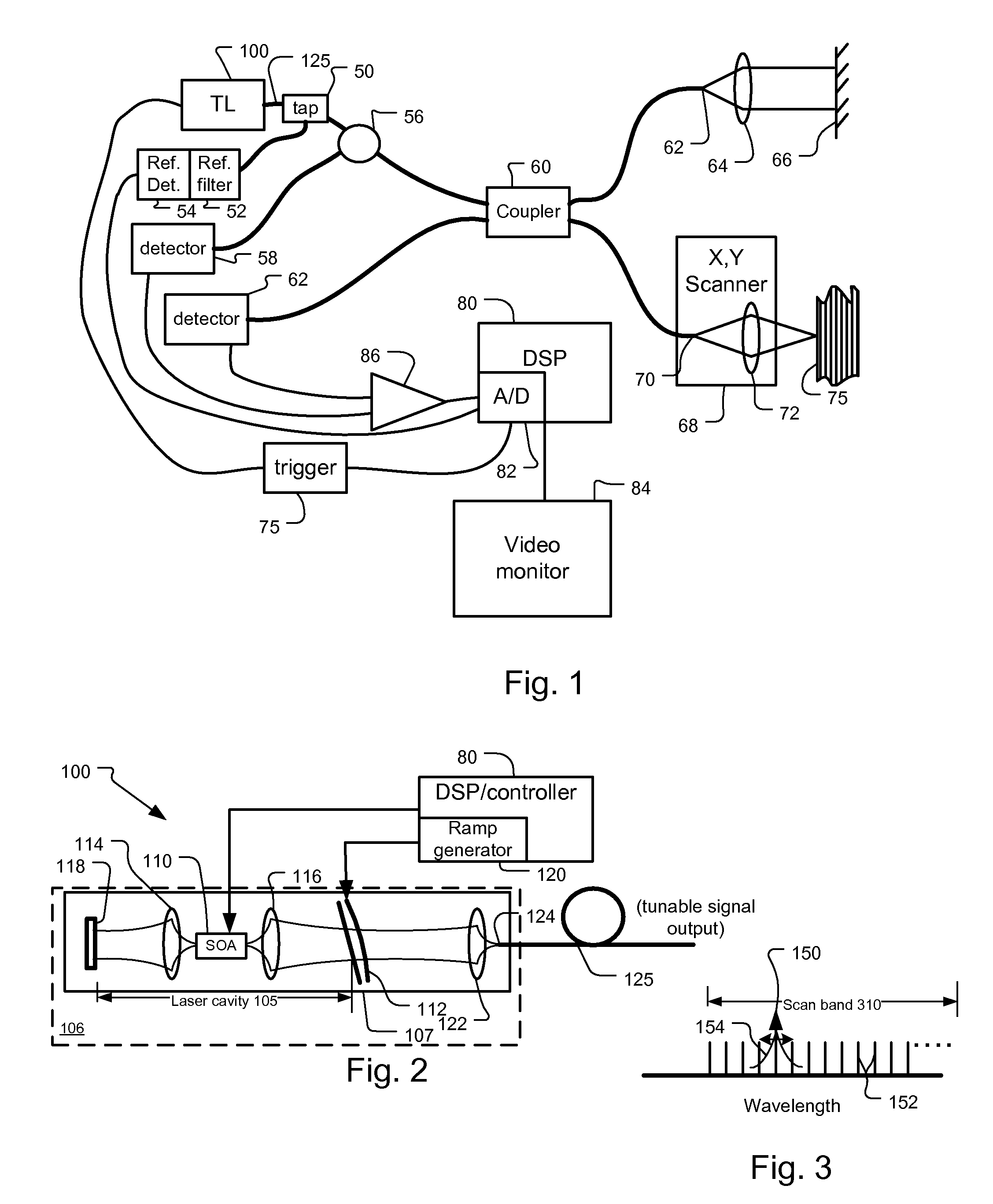
[0035]FIG. 2 shows the tunable semiconductor laser 100 according to the invention.

[0036]In more detail, the tunable laser 100 comprises a semiconductor gain chip 110 that is paired with a microelectromechanical (MEMS) angled reflective Fabry-Perot tunable filter 112 to create external cavity tunable laser (ECL).

[0037]The semiconductor optical amplifier (SOA) chip 110 is located within a laser cavity 105. In the current embodiment, both facets of the SOA chip are angled and anti-reflection (AR) coated, providing parallel beams from the two facets.

[0038]Specifically, each end facet of the SOA 110 has associated lenses 114, 116 that are used to couple the light exiting from either facet of the SOA 110. The first lens 114 couples the light between the back facet of the SOA 110 and a mirror 118. Light exiting out the front facet of the SOA 110 is coupled by a second lens 116 to the reflective Fabry-Perot tunable filter 112.

[0039]The angled reflective Fabry-Perot filter is a multi-spatial...

second embodiment

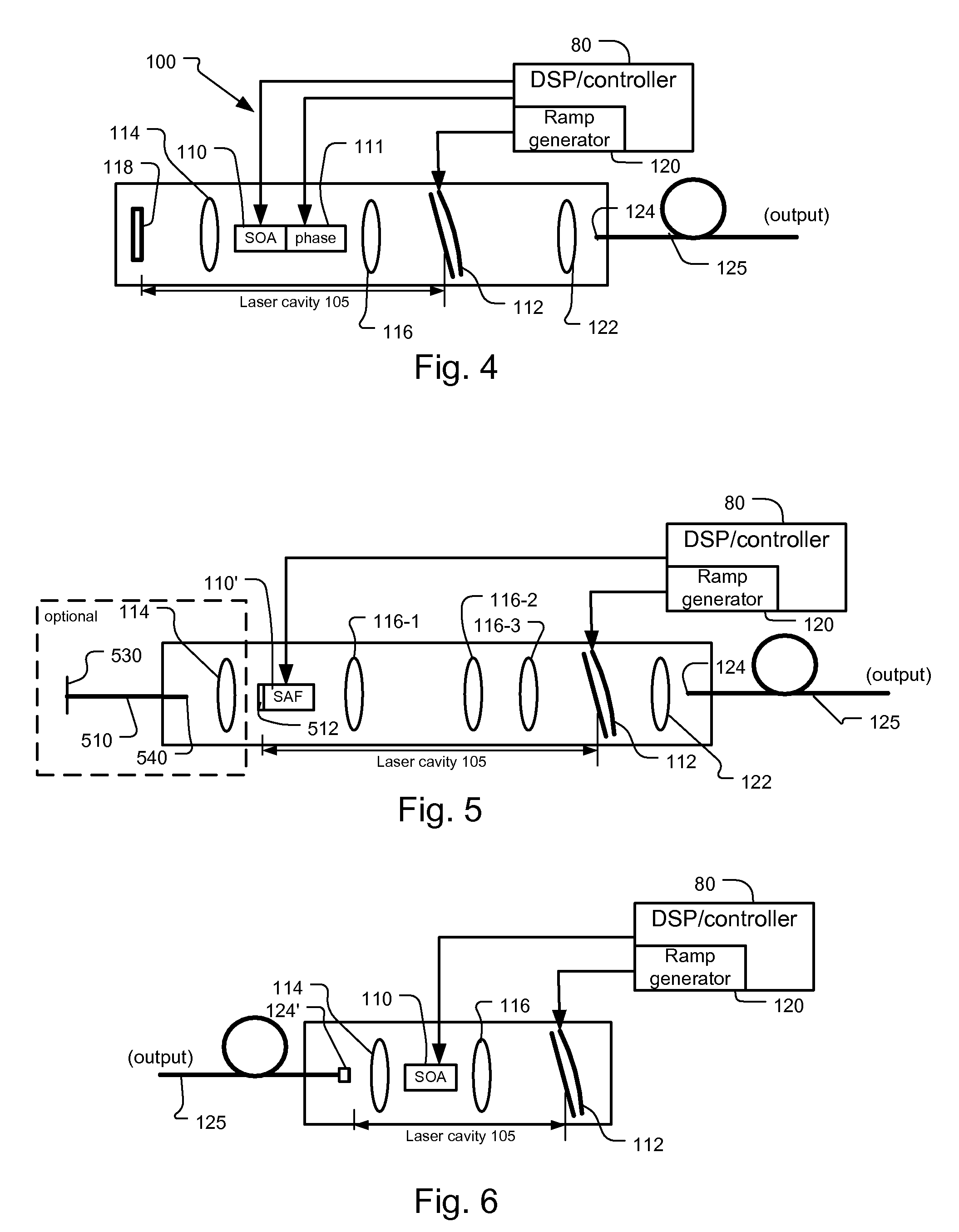
[0047]FIG. 4 shows the mode hopping tunable laser 100. This includes a second semiconductor chip section 111 that functions as an intra cavity phase or dispersion compensator, which is integral with the semiconductor gain medium in a preferred embodiment. Specifically, there is a certain amount of dispersion during scanning, which implies variation of cavity mode frequency spacing. The cavity 105 is not all air; there is refractive index dispersion in the laser chip, lenses, optical coatings. Also, laser threshold changes over the tuning range. Thus, there will typically be higher carrier density inside the gain chip 110, when it is tuned to the edges of the spectrum. This increased carrier density decreases the chip's refractive index and thereby causes a dispersion-like effect.

[0048]The phase compensator 111 controls its refractive index and thus the optical length of the cavity as compensation.

[0049]In other embodiments, the compensator includes an electro-optic medium.

[0050]In o...

third embodiment

[0051]FIG. 5 shows the mode hopping tunable laser 100. This uses a reflective SOA or single angled facet (SAF) chip 110′. Specifically, the back normal facet 512 of the semiconductor amplifier 110′ is reflective to define one end of the laser cavity 105. On the front angled non-reflective facet, a series of three lenses 116-1, 116-2, 116-3 is used to collimate the output of the semiconductor amplifier and relay it to the tunable filter 112, thereby yielding the laser cavity with the desired length. Also in one implementation, light output through fiber 510 is taken, alternatively or in addition to output fiber 125, through the back facet 512 of the reflective optical amplifier SAF 110′. This is used to provide an alternative output of the tunable laser or a second laser output to serve as a possible input to the trigger circuit 75, see FIG. 1.

[0052]In a variant design for longer laser cavities, the reflective SOA 110′ is replaced with an SOA having antireflection (AR) coated front a...


PUM


Abstract

A frequency swept laser source that generates an optical signal that is tuned over a spectral scan band at single discrete wavelengths associated with longitudinal modes of the swept laser source. Laser hopping over discrete single cavity modes allows long laser coherence length even under dynamic very high speed tuning conditions. A ramp drive to the laser is used to linearize laser frequency tuning. A beam splitter is used to divide the optical signal between a reference arm leading to a reference reflector and a sample arm leading to a sample. A detector system detects the optical signal from the reference arm and the sample arm for generating depth profiles and images of the sample.

Description

RELATED APPLICATIONS[0001]This application claims the benefit under 35 USC 119(e) of U.S. Provisional Application No. 60 / 968,185, filed on Aug. 27, 2007.[0002]This application is related to U.S. application No. ______ filed on an even date herewith, entitled Mode Hopping Swept Frequency Laser for FD OCT and Method of Operation, now U.S. Patent Publication No.: ______, which is incorporated herein by reference in its entirety.BACKGROUND OF THE INVENTION[0003]Optical coherence analysis relies on the use of the interference phenomena between a reference wave and an experimental wave or between two parts of an experimental wave to measure distances and thicknesses, and calculate indices of refraction of a sample. Optical Coherence Tomography (OCT) is one example technology that is used to perform usually high-resolution cross sectional imaging that can provide images of biological tissue structure, for example, on the microscopic scales in real time. Optical waves are sent through an ob...

Claims


Application Information

Patent Timeline
Patent Type & Authority Applications(United States)
IPC IPC(8): H01S3/10
CPCG01N21/4795H01S5/02284H01S5/141H01S5/0687H01S5/0683H01S5/02251
Inventor ATIA, WALID A.KUZNETSOV, MARK E.FLANDERS, DALE C.
Owner AXSUN TECH
Why Eureka
Try Eureka