Coherent optical receiver
- Summary
- Abstract
- Description
- Claims
- Application Information
AI Technical Summary
Benefits of technology
Problems solved by technology
Method used
Image
Examples
first embodiment
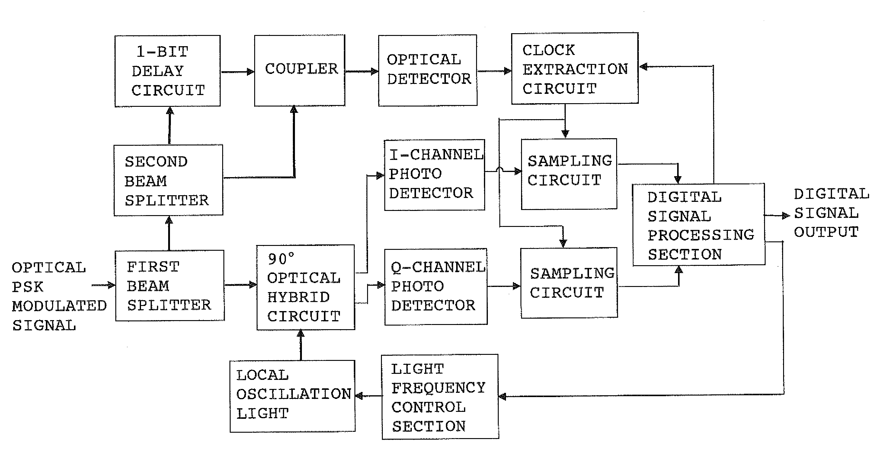
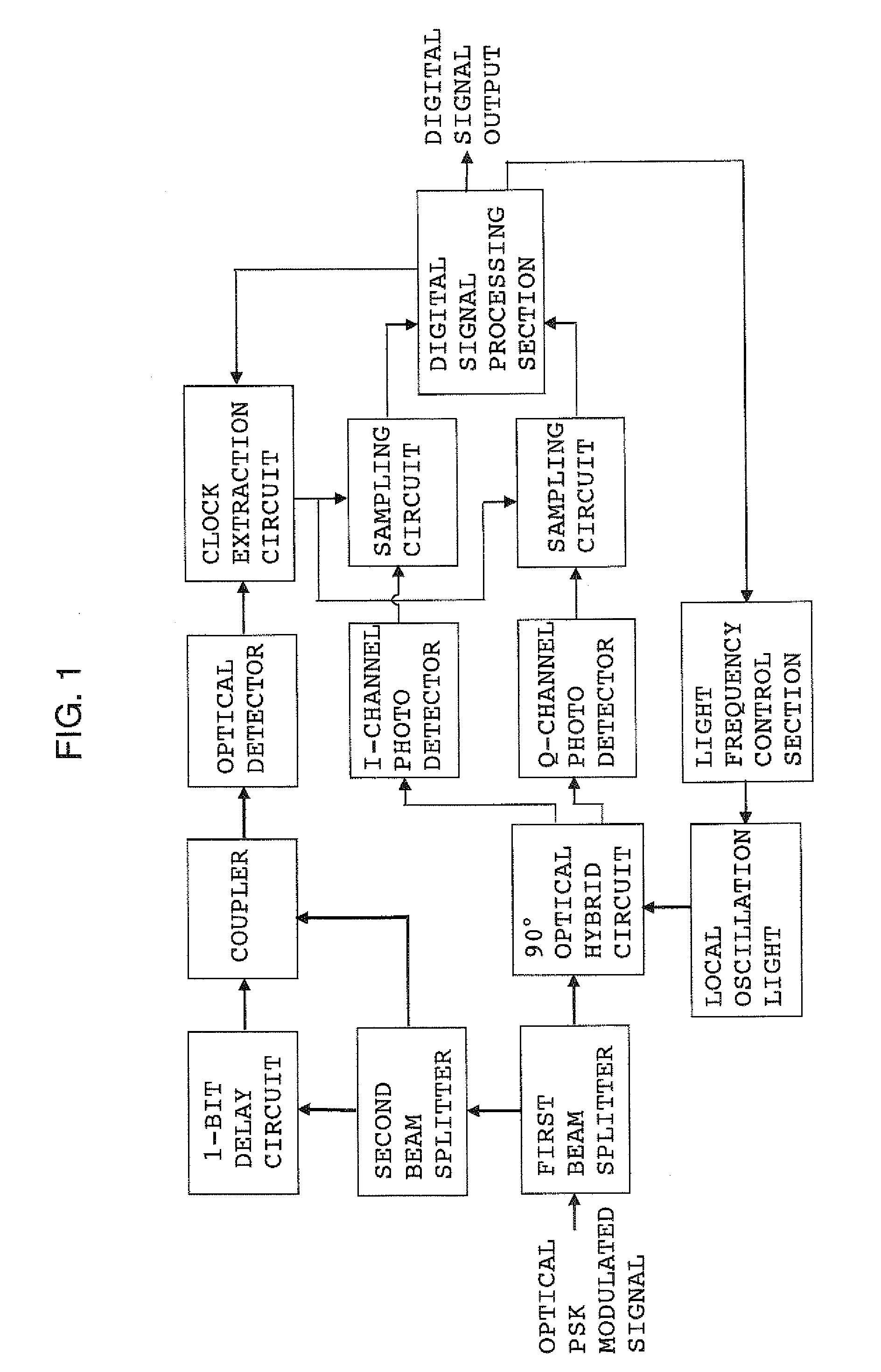
[0022]The present invention will now be described by way of examples. FIG. 1 is a circuit diagram of a coherent optical receiver showing the present invention. FIG. 1 shows an example in which extraction of a clock signal is performed at the optical signal level. An optical PSK (in particular, DPSK or BPSK) modulated signal (light beam) transmitted from a coherent optical transmitter (not shown) is split to two light beams by means of a first beam splitter. One light beam is led to a 90-degree optical hybrid circuit for splitting the input signal light to quadrature components I and Q. The other light beam is led to a second beam splitter. In the 90-degree optical hybrid circuit, the light beam is mixed with local oscillation light, and the resultant quadrature components I and Q are led to photo detectors for I and Q channels. The electric signal output from the photo detectors have a phase difference of 90° therebetween (SIN and COS waves), and carry pieces of information regardin...
second embodiment
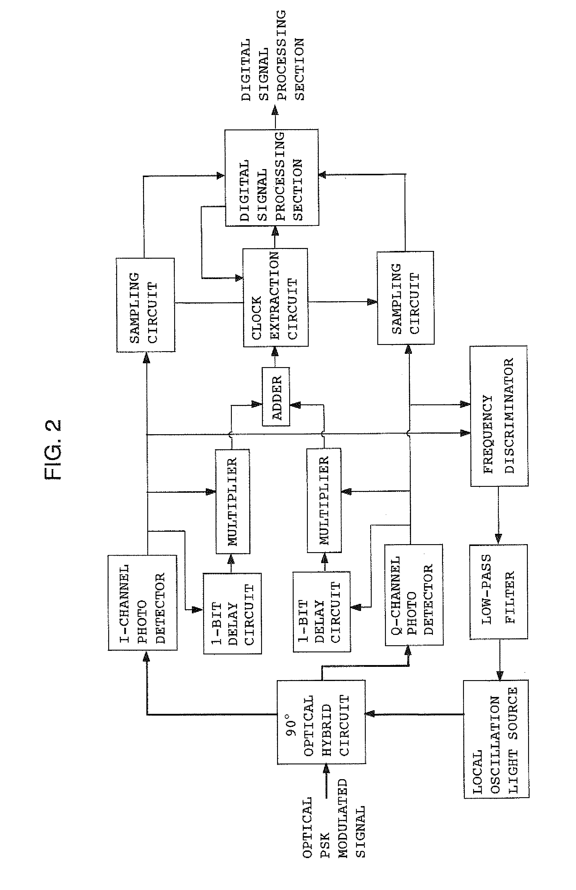
[0028]FIG. 2 is a circuit diagram of a coherent optical receiver showing the present invention. FIG. 2 shows an example in which clock signal extraction is carried out at the electrical signal level, and control of local oscillation light is performed by an analog signal. An optical PSK modulated signal and local oscillation light are mixed together by a 90-degree optical hybrid circuit, and the resultant quadrature components I and Q are led to photo detectors for I and Q channels. The electric signal output from the photo detectors and the same signals having passed through respective 1-bit-delay circuits are multiplied together by respective multipliers. Outputs from these multipliers are added together by an adder, whereby simple demodulation of the signal is carried out. From a signal (demodulated signal) produced as a result of the demodulation, a clock extraction circuit reproduces a clock whose speed is the same as that of the demodulated signal and which is synchronized the...
PUM
 Abstract
Description
Claims
Application Information
 - R&D
- Intellectual Property
- Life Sciences
- Materials
- Tech Scout
- Unparalleled Data Quality
- Higher Quality Content
- 60% Fewer Hallucinations
Browse by: Latest US Patents, China's latest patents, Technical Efficacy Thesaurus, Application Domain, Technology Topic, Popular Technical Reports.
© 2025 PatSnap. All rights reserved.Legal|Privacy policy|Modern Slavery Act Transparency Statement|Sitemap|About US| Contact US: help@patsnap.com


