Film forming method and film forming apparatus

a film forming and film forming technology, applied in the field of film forming methods and film forming apparatuses, can solve the problems of metal contamination in a manufacturing line, multiple substrates b>10/b> processed at the initial stage of the film forming process, and failure to meet the expected specifications, so as to prevent metal contamination in the performance

Inactive Publication Date: 2009-03-05
TOKYO ELECTRON LTD
View PDF4 Cites 20 Cited by
  • Summary
  • Abstract
  • Description
  • Claims
  • Application Information

AI Technical Summary

Benefits of technology

[0009]It is, therefore, an object of the present invention to provide a technique capable of preventing metal contamination in performing, by using an organic silane gas, a film forming process on a target substrate mounted on a mounting table which is made of a ceramic plate containing a metal oxide.

Problems solved by technology

Due to this discrepancy in processing environment, there is likelihood that several substrates 10 processed at the initial stage of the film forming process would not satisfy expected specifications.
Though this is an infinitesimal quantity, it might cause a metal contamination in a manufacturing line.
Thus, problems as follows can occur.
However, since the number of hydrogen atoms contained in a single molecule of the organic silane gas is great, the amount of hydrogen contained (trapped) in the pre-coated film will be also great.

Method used


Image

  • Film forming method and film forming apparatus
  • Film forming method and film forming apparatus
  • Film forming method and film forming apparatus

Examples


first embodiment

[0043]Now, a series of processes performed in accordance with a first embodiment of the present invention will be described with reference to FIGS. 3A to 3C.

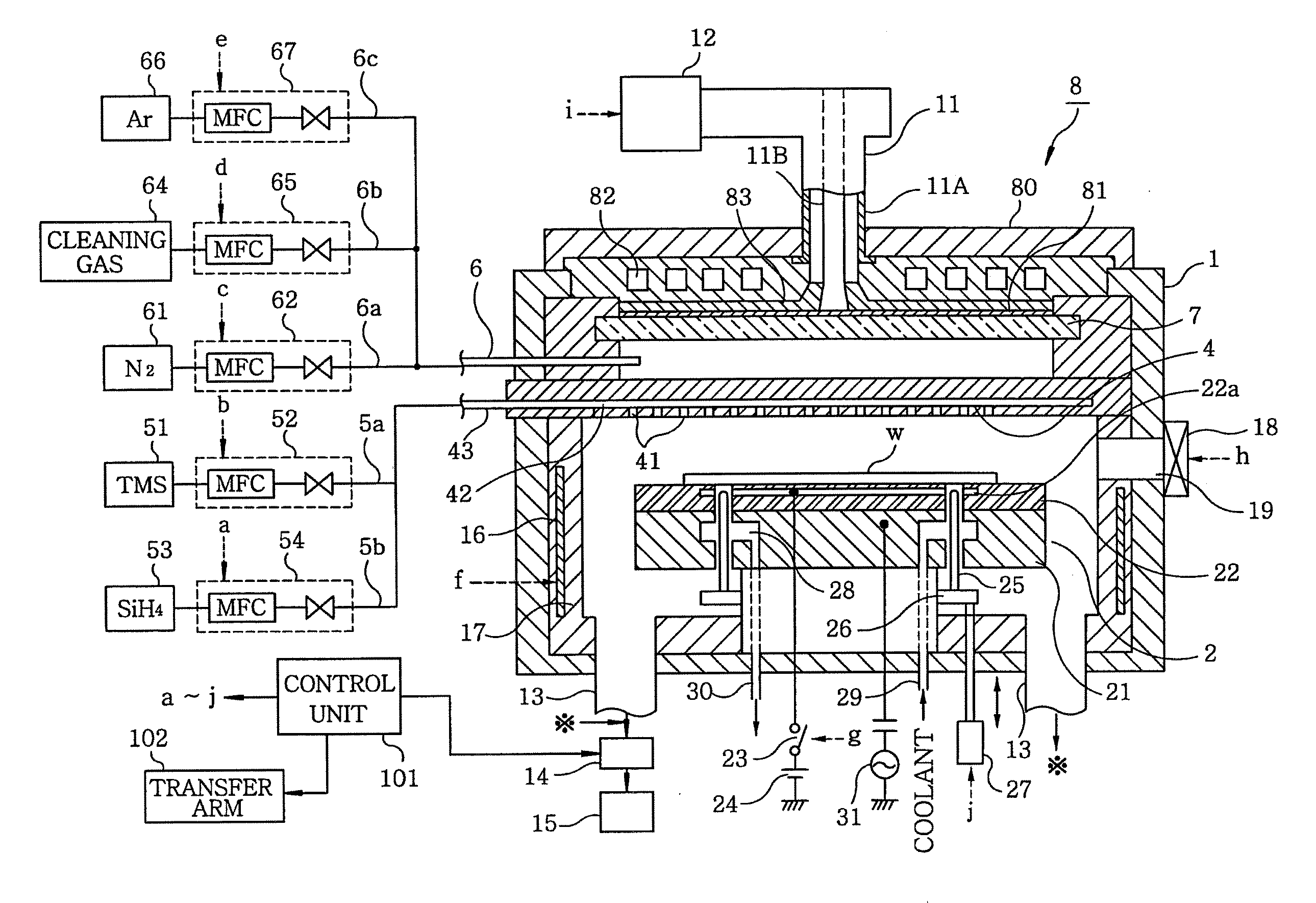
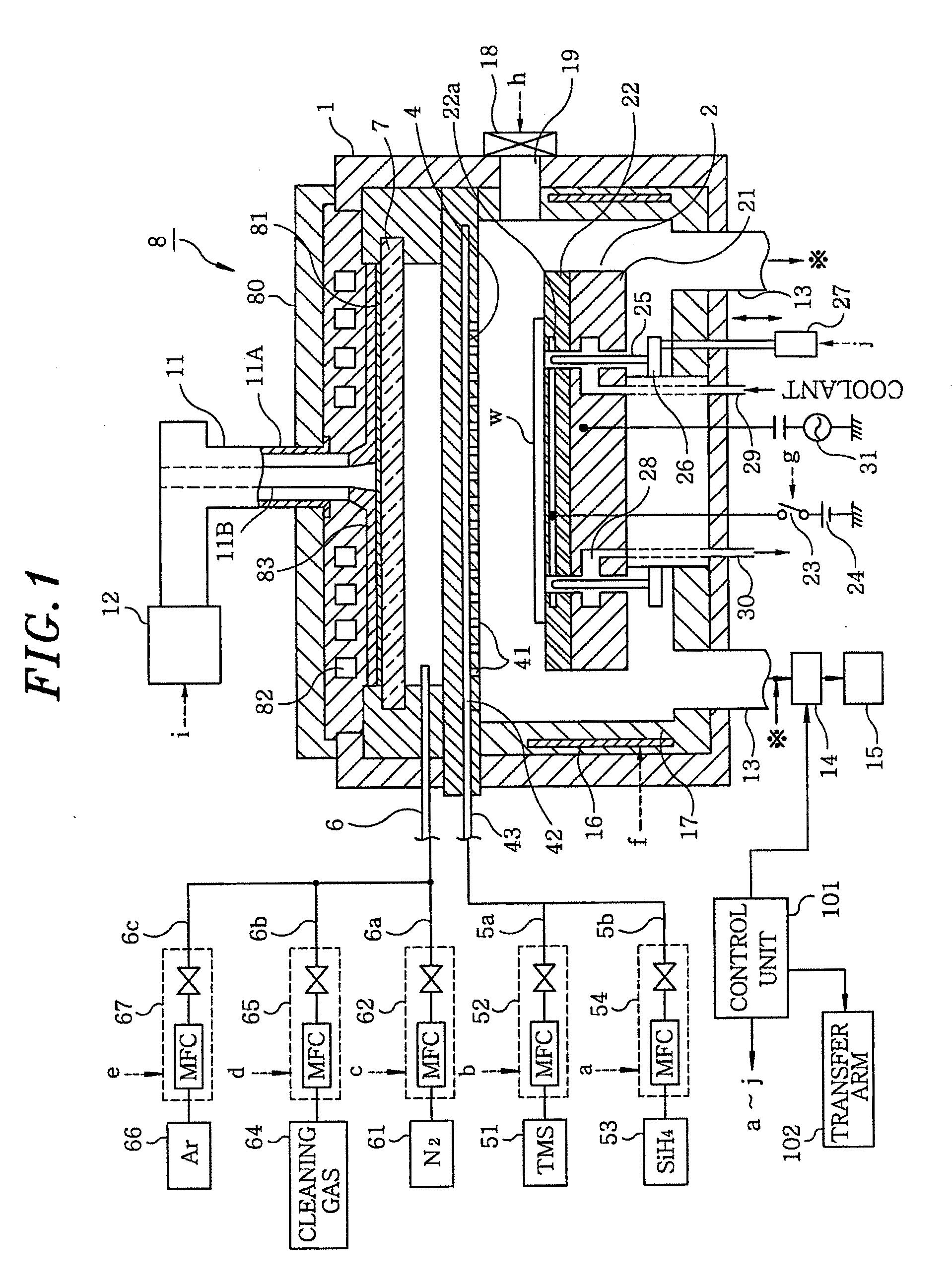
[0044]First, a pre-coating process is performed before a target substrate is loaded into the processing chamber 1. That is, while vacuum-evacuating the processing chamber 1 to a specific pressure level, N2 gas is supplied into the processing chamber 1 via the gas supply line 6 which is the second gas supply unit, and an inorganic silane gas, e.g., monosilane (SiH4) gas is supplied as a processing gas from the first gas supply unit 4 via the gas supply line 43. The internal pressure of the processing chamber 1 is maintained at a specific process pressure level, and the surface temperature of the mounting table 22 is regulated at a certain temperature level, e.g., about 380° C.

[0045]Meanwhile, a high frequency wave (microwave) of, e.g., about 2.45 GHz and 2000 W is supplied from the microwave generator 12. The microwave propagates...

second embodiment

[0053]Now, a series of processes performed in accordance with a second embodiment of the present invention will be explained with reference to FIGS. 4A to 5C.

[0054]First, a pre-coating process is performed before a target substrate is loaded into the processing chamber 1. As in the first embodiment, by using SiH4 gas and N2 gas, a Si3N4 film 200 is formed on the surface of the mounting table 22, the inner wall of the processing chamber 1, the surface of the first gas supply unit 4 and so forth as a first pre-coat film in a thickness of, e.g., about 5 nm, as illustrated in FIG. 4A.

[0055]Subsequently, as illustrated in FIG. 4B, by means of the transfer arm 102 (see FIG. 1), a dummy substrate D having the same size as a wafer W is mounted on the mounting table 22 which is coated with the Si3N4 film 200 through the pre-coating process described above. The dummy substrate D mounted on the mounting table 22 is electrostatically attracted to and held on the mounting table 22 by a Coulomb f...


PUM

PropertyMeasurementUnit
thicknessaaaaaaaaaa
frequencyaaaaaaaaaa
temperatureaaaaaaaaaa

Abstract

A film forming method is characterized in that the method is provided with a step of introducing a processing gas including inorganic silane gas into a processing chamber, in which a mounting table composed of ceramics including a metal oxide is arranged, and precoating an inner wall of the processing chamber including a surface of the mounting table with a silicon-containing nonmetal thin film; a step of mounting a substrate to be processed on the mounting table precoated with the nonmetal thin film; and a step of introducing a processing gas including organic silane gas into the processing chamber, and forming a silicon-containing nonmetal thin film on a surface of the substrate mounted on the mounting table.

Description

FIELD OF THE INVENTION[0001]The present invention relates to a film forming method and a film forming apparatus for forming a nonmetal film on a surface of a target substrate using an organic silane gas after performing a precoating process for attaching a thin film to surfaces of components in a processing chamber, including a surface of a mounting table, in advance.BACKGROUND OF THE INVENTION[0002]A film forming process is one of semiconductor manufacturing processes. The film forming process typically involves activating a processing gas in a vacuum atmosphere by, for example, converting it into plasma or thermally decomposing it; and depositing active species or reaction products on a substrate surface. A film forming apparatus for performing such a film forming process includes a mounting table disposed in a processing chamber which is configured as a vacuum chamber. As the mounting table, there can be used a ceramic plate which incorporates therein a temperature control unit f...

Claims


Application Information

Patent Timeline
Patent Type & Authority Applications(United States)
IPC IPC(8): C23C16/36C23C16/42
CPCC23C16/4404C23C16/4581H01L21/3185H01L21/02274H01L21/02167H01L21/20H01L21/205
Inventor KAMESHIMA, TAKATOSHIKAWAMURA, KOHEIKOBAYASHI, YASUO
Owner TOKYO ELECTRON LTD
Why Eureka
Try Eureka