
Ceramic-Resin Composite Roll and Production Method of the Same

a technology of composite rolls and ceramic resins, applied in the direction of press sections, roads, traffic signals, etc., can solve the problems of insufficient sealing effect, insufficient impact resistance, abrasion resistance, chemical resistance and corrosion resistance, etc., to achieve superior strength, easy penetration, and high calorific value

Inactive Publication Date: 2009-03-12
YAMAUCHI CORP
View PDF3 Cites 1 Cited by
  • Summary
  • Abstract
  • Description
  • Claims
  • Application Information

AI Technical Summary

Benefits of technology

[0008]The present invention was made in order to solve the above problem and it is an object of the present invention to provide a ceramic-resin composite roll superior in impact resistance, abrasion resistance, chemical resistance and corrosion resistance, and its production method.

Problems solved by technology

When the chemicals and water penetrate into the roll, the thermally sprayed ceramic film and the roll core are likely to be corroded, which causes the roll to be damaged.
Therefore, although a sealing process is performed on the surface of the ceramic roll in general, its sealing effect is not sufficient at the present.
However, it has been found that the impact resistance, abrasion resistance, chemical resistance and corrosion resistance are not sufficiently provided only by filling the surface layer of the thermally sprayed ceramic film with the organic polymer material.
Thus, it was difficult to impregnate the thermally sprayed ceramic film with the resin sufficiently.
In this case, even when the mixture material is used, since the voids are generated due to spraying, sufficient sealing effect cannot be provided.
In addition, when the mixture material is thermally sprayed, since the plastic intervenes in not only the voids among the ceramic particles but also in a bonded part among the ceramic particles, the fused bonding of the ceramic particles becomes insufficient and the ceramic particles are likely to be removed, so that the sprayed film is rather inferior in strength to the ceramic.

Method used


Image

  • Ceramic-Resin Composite Roll and Production Method of the Same
  • Ceramic-Resin Composite Roll and Production Method of the Same
  • Ceramic-Resin Composite Roll and Production Method of the Same

Examples


working example 1

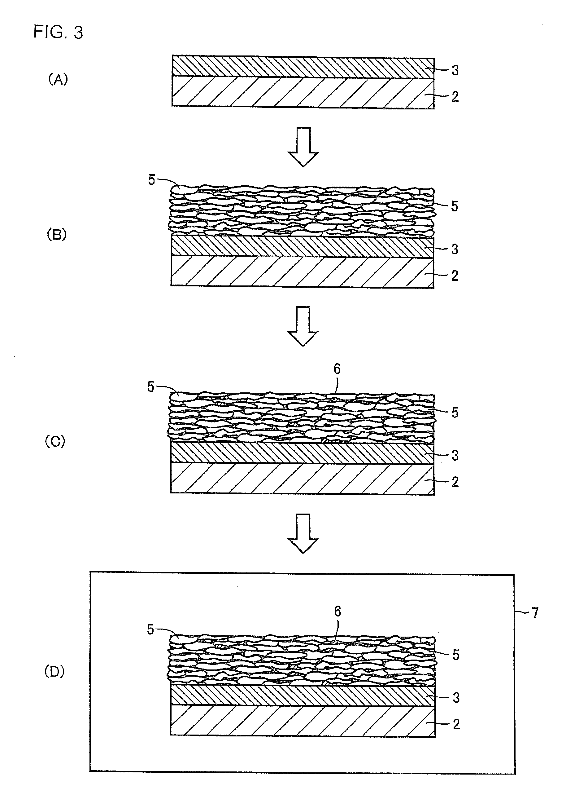
[0037]First, the surface of a cast iron roll core having a length of 5100 mm, a surface length of 3400 mm and a diameter of 550 mm was cleaned and defatted and roughened by sandblasting. Then, a nickel-chrome alloy was thermally sprayed onto the surface of the roll core by an arc spraying equipment, whereby a foundation layer having a thickness of 0.5 mm was formed. Then, while the roll core having the foundation layer was rotated, alumina-titania (Al2O3-13% TiO2) powder having an average grain diameter of 35 μm was thermally sprayed by a water-stabilized plasma spraying equipment, whereby a thermally sprayed ceramic film having a thickness of 1.2 mm and a porosity of 8% was formed.

[0038]Then, the thermally sprayed ceramic roll was preheated to 70° C. and a liquid epoxy resin raw material that was preheated to 70° C. was applied from the surface of the roll so that the roll was impregnated with it. The used epoxy resin raw material was a mixed solution of 100 parts by mass of Araldi...


PUM

PropertyMeasurementUnit
Thermosettingaaaaaaaaaa

Abstract

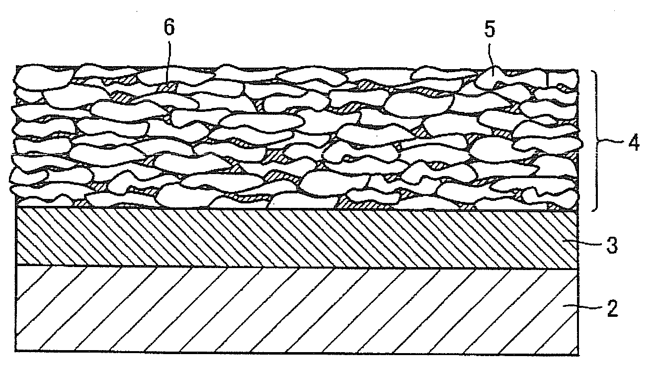
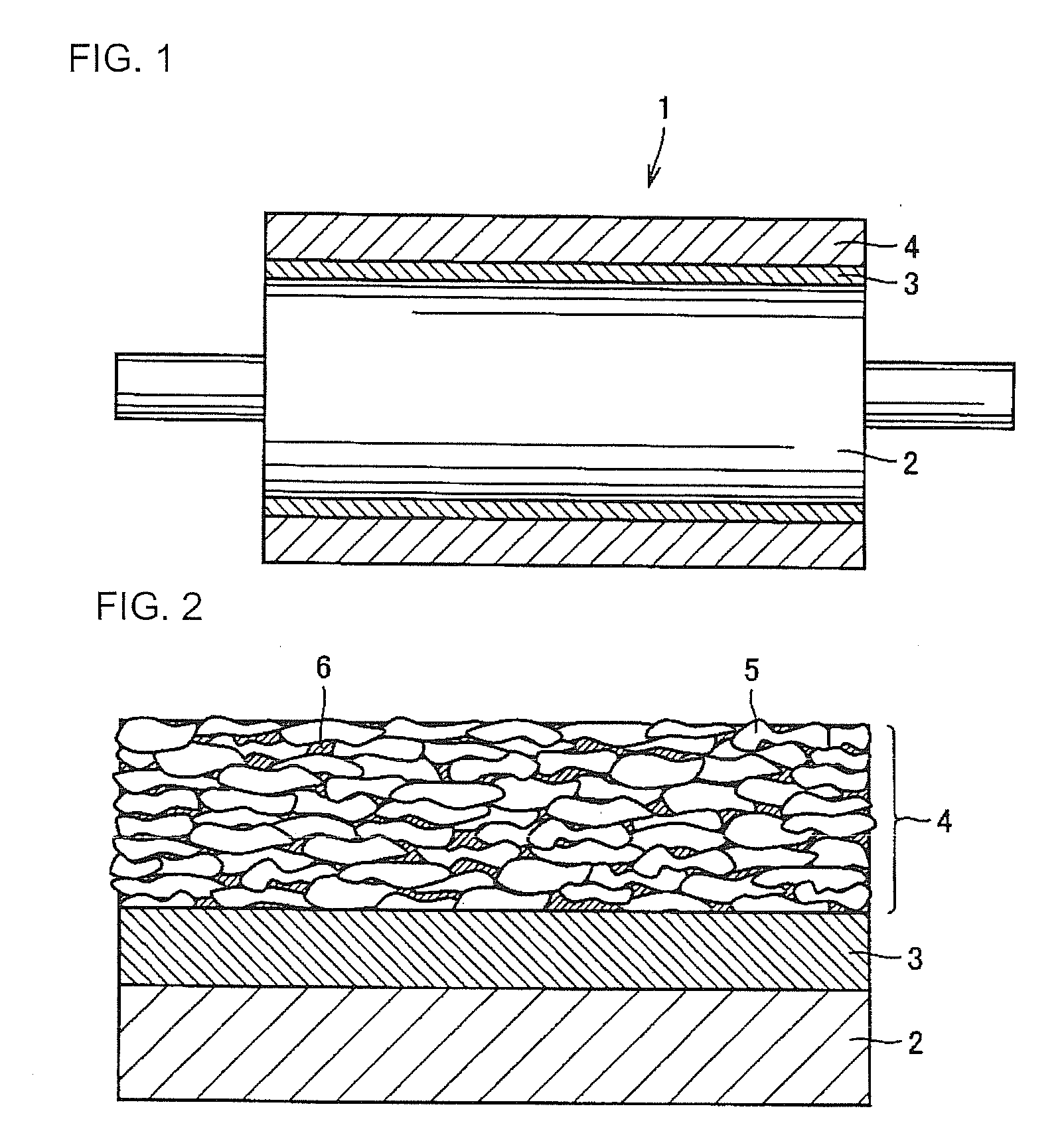
A ceramic-resin composite roll (1) comprises a metal roll core (2), a foundation layer (3) formed on the outer circumferential surface of the metal roll core (2) and a thermally sprayed ceramic film (4) formed on the outer circumferential surface of the foundation layer (3). The thermally sprayed ceramic film (4) includes a ceramic particle layer in which adjacent ceramic particles are fused and bonded to each other and a layer of a resin (6) penetrating into the spaces among the ceramic particles (5) from the surface of the ceramic particle layer to the surface of the foundation layer (3).

Description

TECHNICAL FIELD[0001]The present invention relates to a ceramic-resin composite roll that can be used in the various kinds of industries and more particularly, to a ceramic-resin composite roll that is superior in impact resistance, abrasion resistance, chemical resistance and corrosion resistance and can be used as a paper making roll, and its production method.BACKGROUND ART[0002]A ceramic roll having a thermally sprayed ceramic film is used in a pressing part, a coating part, and a wiring part in a paper making process. Since the ceramic particles in the thermally sprayed ceramic film are fused and bonded to each other strongly, the ceramic roll is superior in strength and abrasion resistance in general as a whole.[0003]Meanwhile, since there are spaces among the fused and bonded ceramic particles in the thermally sprayed ceramic film, chemicals and water contained in a pulp solution are likely to penetrate into a roll surface. When the chemicals and water penetrate into the roll...

Claims


Application Information

Patent Timeline
IPC IPC(8): B32B3/14C23C4/04
CPCD21F3/08Y10T428/24372F16C13/00
Inventor SHIMAZAKI, HIROYA
Owner YAMAUCHI CORP
Learn More