Glass Package That Is Hermetically Sealed With a Frit and Method of Fabrication

a glass package and frit technology, applied in the direction of solid-state devices, electrical appliances, basic electric elements, etc., can solve the problems of difficult to develop a sealing process, difficult to reduce the thickness variation, and inability to maintain the seal for a long time. , to achieve the effect of avoiding thermal damage to the oled and reducing the variation of thickness

Inactive Publication Date: 2009-03-12
CORNING INC
View PDF6 Cites 51 Cited by
  • Summary
  • Abstract
  • Description
  • Claims
  • Application Information

AI Technical Summary

Benefits of technology

[0014]The present invention includes a hermetically sealed OLED display, and display preform, and method for manufacturing the hermetically sealed OLED display and display preform. Basically, the hermetically sealed OLED display is manufactured by providing a first substrate plate and a second substrate plate, depositing a frit onto the second substrate plate and pre-sintering the deposited frit. Any need to grind the sintered frit to reduce thickness variations is avoided by 1) using a frit comprising a base glass selected from Fe2O3 or rare earth metal oxide doped Sb2O3—V2O5—P2O5 glasses of a controlled particle size distribution and, optionally, a CTE matching filler of a controlled particle size distribution, and 2) pre-sintering the deposited frit in an atmosphere which is less oxidizing than air. OLEDs are deposited onto the first substrate plate. An irradiation source (e.g., laser or infrared light) is then used to heat the frit which softens and forms a hermetic seal that bonds the first substrate plate to the second substrate plate and also protects the OLEDs. This enables the frit to soften and form the hermetic seal while avoiding thermal damage to the OLEDs.

Problems solved by technology

However, the traditional OLED displays and in particular the electrodes and organic layers located therein are susceptible to degradation resulting from interaction with oxygen and moisture leaking into the OLED display from the ambient environment.
Unfortunately, in the past it was very difficult to develop a sealing process to hermetically seal the OLED display.
Although these types of seals usually provide good mechanical strength, they can be very expensive and there are many instances in which they have failed to prevent the diffusion of oxygen and moisture into the OLED display.
However, the resulting seal is not durable in a wide range of temperatures because of the substantial differences between the coefficients of thermal expansions (CTEs) of the glass plates and metal in the OLED display.
The need for grinding increases the cost and complexity of the OLED manufacturing process.

Method used


Image

  • Glass Package That Is Hermetically Sealed With a Frit and Method of Fabrication
  • Glass Package That Is Hermetically Sealed With a Frit and Method of Fabrication
  • Glass Package That Is Hermetically Sealed With a Frit and Method of Fabrication

Examples


example 1

[0042]Flow-buttons were prepared from base glass composition (mole %): Sb2O3, 23.5; V2O5, 47.5; P2O5, 27.0; Al2O3, 1.0; TiO2, 1.0 and filler composition (mole %): Li2O, 25.0; Al2O3, 25.0; SiO2, 50.0, and then pre-sintered in air, one at 400° C. and the other at 450° C. The 400° C. pre-sintered flow button was brown in color, while the 450° C. pre-sintered flow button was black. The flow buttons were then immersed in equal amounts of 90° C. D.I. (de-ionized) H2O for 48 hours. There was a substantial difference in aqueous durability between the two pre-sintering treatments: the 400° C. flow button exhibited sufficient chemical attack to turn the water a dark black coloration, and the 450° C. pre-sintered flow button exhibiting only minor chemical attack, turning the water a light green. The extent of water discoloration is related to the extent of vanadium leaching from the flow button and the resistance to H2O chemical attack.

example 2

Controlled Atmosphere Pre-Sintering

[0043]The major observable change associated with the lowering of pre-sintering temperature from 450° C. to 400° has to do with the color of the frit. For pre-sintering in air, frits heated to 450° C. were black, suggesting reduced vanadium species (V+3 or V+4) in the frit. Frits pre-sintered at 400° C. in air were invariably brown, suggesting V+5 as the dominant oxidation state. Direct confirmation of the color-oxidation state relationship for these frits could, unfortunately, not be obtained with certainty, since the available analytical techniques such as NMR, EPR, or XPS were either unable to detect all three oxidation states, or else gave irreproducible results on seemingly identical samples. However, indirect support for the color-oxidation state relationship exists since samples pre-sintered at 400° C. in increasingly oxidizing atmospheres ranging from 100% N2, 80% N2 / 20% O2, 50% N2 / 50% O2, 20% N2 / 80% O2, and 100% O2 turned increasingly brow...

example 3

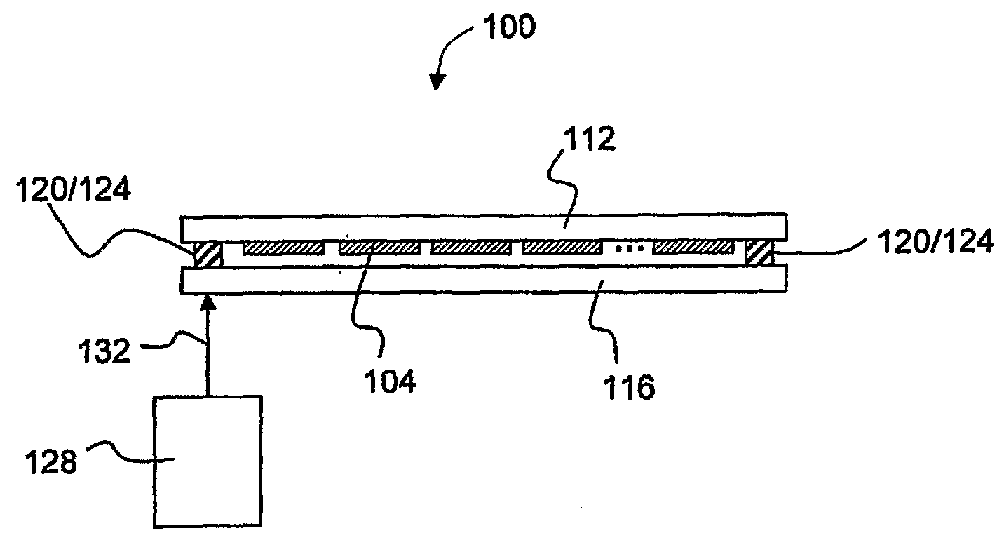
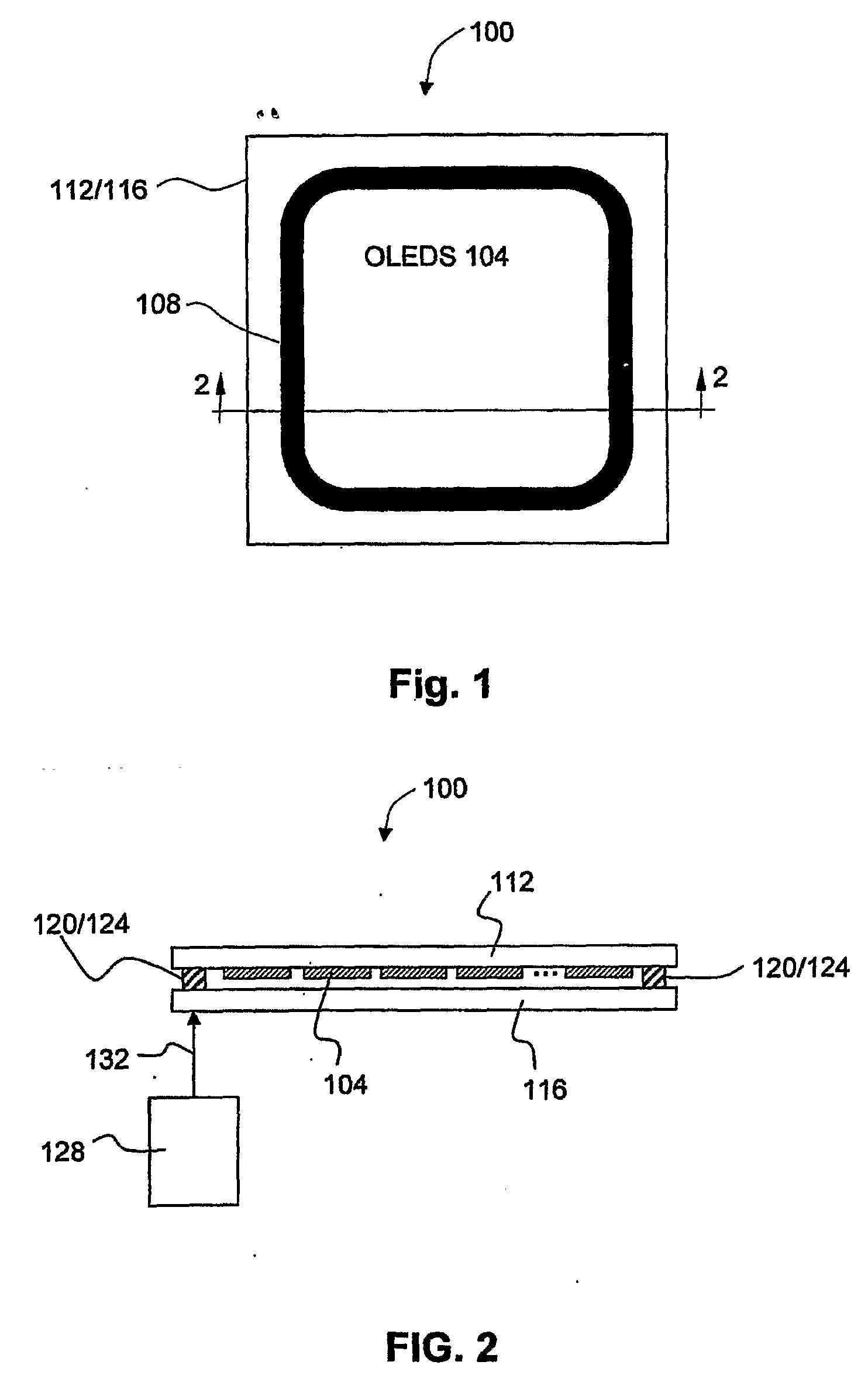
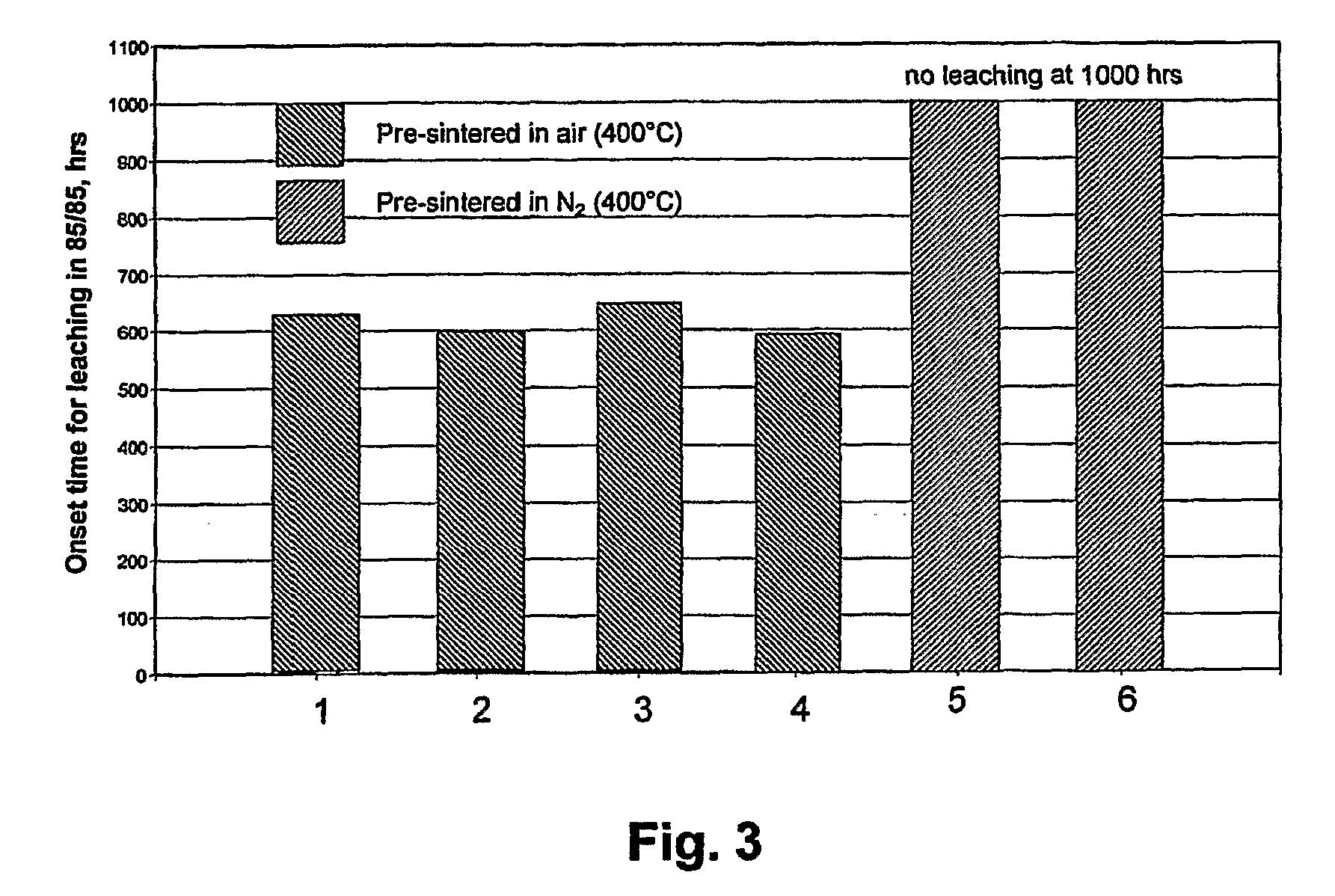
[0044]This example demonstrates that pre-sintering under a less oxidizing atmosphere than air increases the environmental durability of the small particle size frits of the present invention. Two different sheets, each containing nine cells, or glass packages, made with SVP frits which did not contain Fe2O3, Nd2O3 or other rare earth metal oxides were sealed using a laser and then placed into an 85 / 85 environment. Prior to sealing, each sheet was initially fired to 325° C. in air to burn off all frit binder volatiles. Following this step, one sheet was pre-sintered to 400° C. in air, while the other sheet was pre-sintered to 400° C. in 100% N2. Oxygen measurements of the furnace atmosphere during the 100% N2 run indicated an O2 level of approximately 20 ppm. After pre-sintering and subsequent laser sealing, the sheets were placed in an 85 / 85 environmental chamber. Each sheet was then examined about every 48 hours to assess when leaching was initiated on any of the cells. The N2 pre-...


PUM

PropertyMeasurementUnit
wt. %aaaaaaaaaa
wt. %aaaaaaaaaa
mean particle size distributionaaaaaaaaaa

Abstract

A hermetically sealed glass package preform is provided comprising a glass substrate; a frit comprising 65-100 wt. % of a base glass and about 0-35 wt. % of a filler; wherein the base glass comprises: about 0-5 mole % K2O; about 0-35 mole % Sb2O3; about 0-20 mole % ZnO; about 10-40 mole % P2O5; about 10-60 mole % V2O5; about 0-5 mole % TiO2; about 0-5 mole % B2O3; about 0-5 mole % SiO2; about 0-5 mole % WO3; and about 1-10 mole % of a metal oxide selected from the group consisting of Fe2O3, Nd2O3, La2O3, Ce2O4, Pr6O11, Er2O3, and CeO2; wherein the base glass has a mean particle size distribution of less than about 3 μm; and wherein the filler has a mean particle size distribution of between about 3 and 7 μm. The frit is sintered in an atmosphere less oxidizing than air at a temperature of between about 390° C. to 415° C.

Description

CROSS REFERENCE TO RELATED APPLICATIONS[0001]This application claims the benefit under 35 USC §119(e) of U.S. Provisional Application No. 60 / 748,301, filed on Dec. 6, 2005.BACKGROUND OF THE INVENTION[0002]1. Field of the Invention[0003]The present invention relates to hermetically sealed glass packages that are suitable to protect thin film devices that are sensitive to the ambient environment. Some examples of such devices are organic light emitting diode (OLED) displays, sensors, and other optical devices. The present invention is demonstrated using OLED displays as an example.[0004]2. Description of Related Art[0005]OLEDs have been the subject of a considerable amount of research in recent years because of their use and potential use in a wide variety of electroluminescent devices. For instance, a single OLED can be used in a discrete light emitting device or an array of OLEDs can be used in lighting applications or flat-panel display applications (e.g., OLED displays). The tradi...

Claims


Application Information

Patent Timeline
Patent Type & Authority Applications(United States)
IPC IPC(8): C03C8/24C03C8/08
CPCC03C1/026H01L51/5237C03C8/24C03C3/21H10K50/8426C03C8/02C03C8/08C03C8/04
Inventor LAMBERSON, LISA ANNMORENA, ROBERT MICHAEL
Owner CORNING INC
Why Eureka
Try Eureka