

Medical Scaffold, Methods of Fabrication and Using Thereof
a technology of medical scaffolds and scaffolds, applied in the field of electrospun elements, can solve the problems of unsatisfactory immunological rejection, blood coagulation and/or tissue hypertrophy, and synthetic scaffolds lack sufficient bioaffinity and compatibility, and fail to provide sufficient biological signals which guide cell growth
- Summary
- Abstract
- Description
- Claims
- Application Information
AI Technical Summary
Benefits of technology
Problems solved by technology
Method used
Image

Examples
example 1
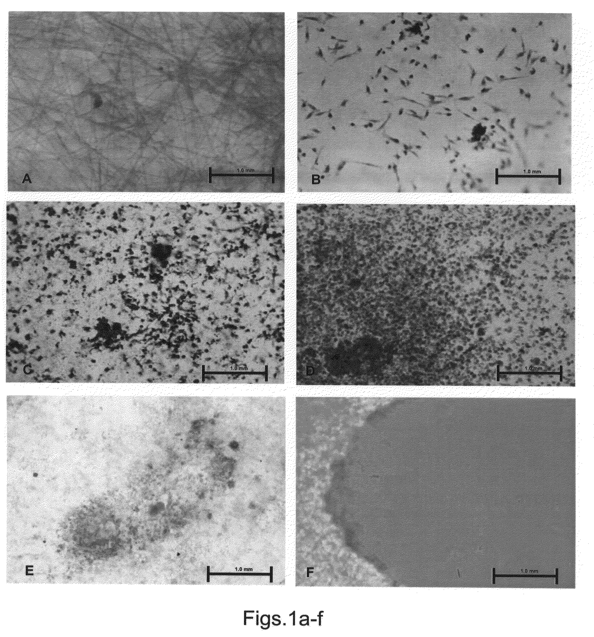
PCL-PLA Electrospun Scaffolds are Highly Suitable for Guided Bone Regeneration
[0284]Materials and Experimental Methods
[0285]Electrospinning of scaffolds—Electrospun nanofibrous scaffolds were prepared from the following polymers: Poly(e-caprolactone) (PCL) with an average molecular weight of 80 kDa (Aldrich, USA) was dissolved in DMF (di-methyl formamide) / DCM(di-chloromethane) 25:75 to obtain 10% wt % solution.
[0286]Mixtures of PCL:PLA (3:1 ratio, respectively); PCL:PLA (9:1 ratio, respectively); PCL:PLA (1:3) and Acid hydrolyzed Collagen (1:3 ratio, respectively); PCL:Collagen hydrogel (1:9 ratio, respectively); PCL:PEO (3:1 ratio, respectively), and PCL:PEO (9:1 ratio, respectively). PLGA:PLA (1:1 ratio); PLGA:PCL:PLA (1:1:1 ratio). All numbers represent weight ratios between polymers.
[0287]Briefly, electrospinning was performed by delivering a polymer solution at a constant flow rate (0.5 ml / hour) through a plastic syringe with a capillary metal needle connected to a high voltage...
example 2
Electrospun Elements with a Continuous or Step Wise Gradient of Porosity, Average Pore Size and / or Fiber Weight Per Volume
[0310]The present inventors have uncovered a novel method for controlling the porosity, the average pore size and the average fiber weight per volume of electrospun elements, as follows.
[0311]Formation of gradient porosity, average pore size and / or weight per volume in electrospun elements—Electrospinning is performed by delivering a polymer solution from a syringe with a capillary metal needle connected to a high voltage (several kV) towards a grounded wheel as a collecting electrode.
[0312]It will be appreciated that various parameters affect the porosity, average pore size, average fiber weight per volume, and / or fiber diameter. These include for example, the speed of the wheel to which the collecting electrode is connected, the flow rate of the polymer solution from the syringe, the concentration of the polymer solution in the dispensers (e.g., syringes), the ...
example 3
Perforation of Electrospun Elements
[0320]The present inventors have uncovered experimental conditions suitable for perforating electrospun elements using electrical spark, laser beam and / or mechanical perforation.
[0321]An Example of Perforation of Electrospun Elements Using an Electrical Spark
[0322]An electrospun scaffold is made of PCL / PLA at a 3:1 ratio, respectively, as described in Example 1, hereinabove, with a total thickness of 200 μm. The electrospun scaffold can be perforated by passing an electrical spark through the electrospun element. This is performed by positioning the scaffold between an high voltage electrode (e.g., at 18 kV) and the ground electrode. The distance between the electrodes is about 10 mm. Electrical sparks produced between the high voltage electrode and the ground electrode results in holes through the scaffold.
[0323]An Example of Laser Perforation of Electrospun Elements
[0324]An electrospun scaffold is made of PCL / PLA at a 3:1 ratio, respectively, as ...
PUM
| Property | Measurement | Unit |
|---|---|---|
| pore diameter | aaaaa | aaaaa |
| pore diameter | aaaaa | aaaaa |
| porosity | aaaaa | aaaaa |
Abstract
Description
Claims
Application Information