Dental Optical Coherence Tomograph

a tomograph and optical coherence technology, applied in the field of optical coherence tomograph apparatus, can solve the problems of inability to obtain internal information such as the information about teeth, the inability to know the internal structure of the subject in a three-dimensional way, and the annual exposure dose, so as to achieve the effect of high-speed imaging and simple structur

Inactive Publication Date: 2009-03-26
SHOFU INC
View PDF5 Cites 141 Cited by
  • Summary
  • Abstract
  • Description
  • Claims
  • Application Information

AI Technical Summary

Benefits of technology

[0015]According to the present invention, it is possible to provide an optical coherence tomography apparatus having a simple structure, capable of performing high speed imaging and being applicable to dental measurements.

Problems solved by technology

Therefore, the internal structure of the subject cannot be known in a three-dimensional way.
In addition, since X rays are harmful to the human body, the annual exposure dose is limited, and they can be handled only by qualified experts.
Intraoral cameras image only the surface of intraoral tissues, and the internal information such as the information about a tooth therefore cannot be obtained.
Like X-ray imaging apparatuses, X-ray CT is harmful to the human body.
Moreover, it has low resolution, and involves large and expensive apparatuses.
MRI has low resolution, and involves large and expensive apparatuses.
Moreover, it cannot image the internal structure of a tooth containing no moisture.
However, there is no photodetector capable of directly measuring the waveform on the temporal axis, because the optical waveform of the measuring light 5 is a phenomenon that is very rapid.

Method used


Image

  • Dental Optical Coherence Tomograph
  • Dental Optical Coherence Tomograph
  • Dental Optical Coherence Tomograph

Examples


embodiment 1

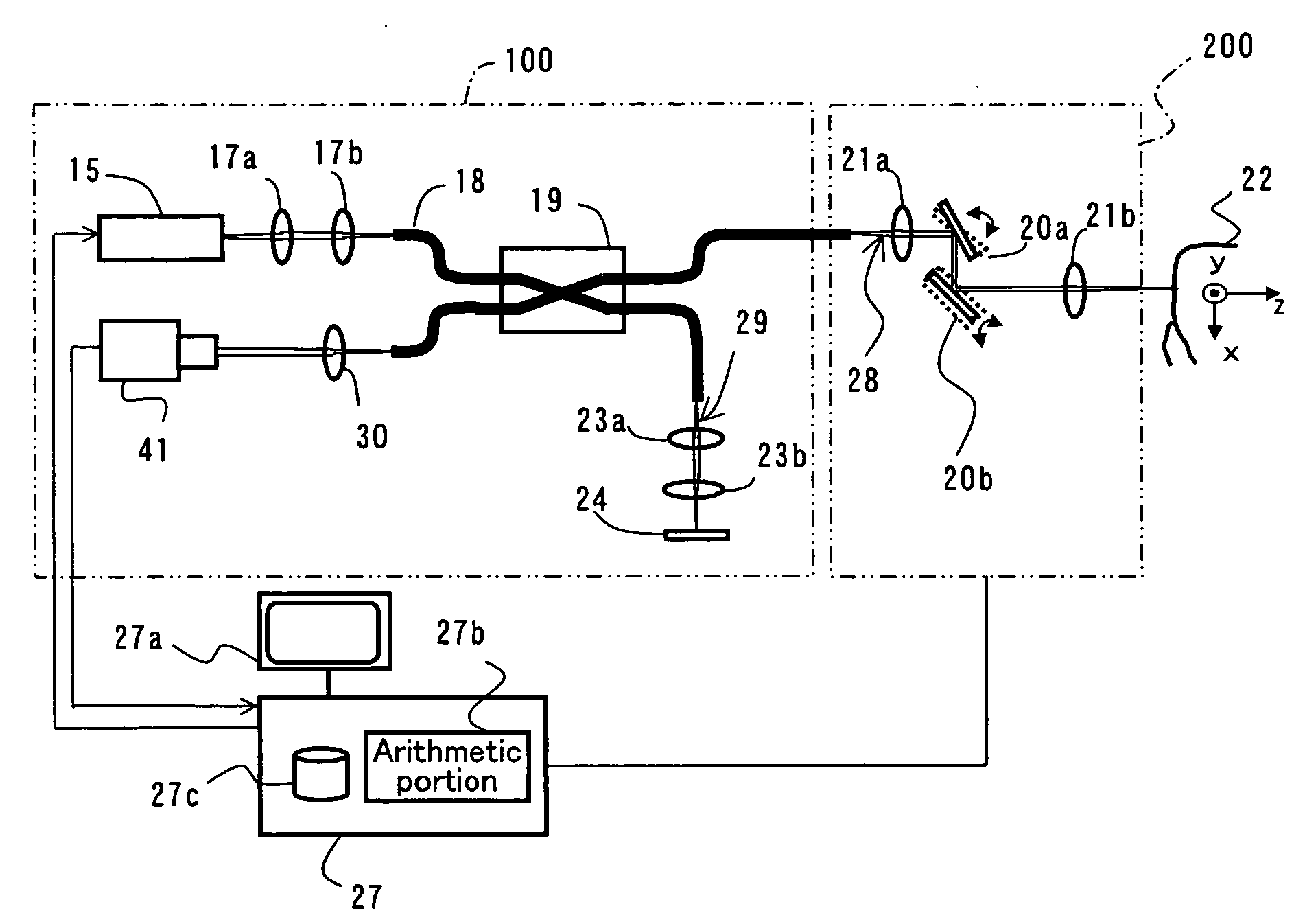
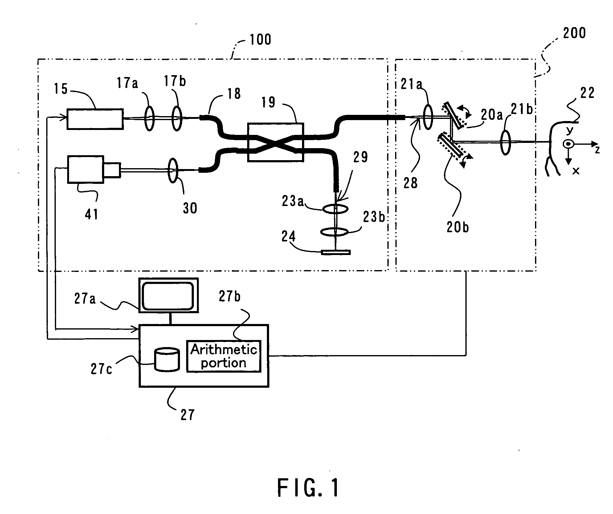
[0076]FIG. 1 is a diagram showing an example of the configuration of a Fourier domain optical coherence tomography apparatus (hereinafter referred to as “FD-OCT apparatus”) according to Embodiment 1. It should be noted that FD-OCT is the abbreviation for Fourier-domain OCT. An FD-OCT apparatus is an OCT apparatus that measures interference light between measuring light emitted from a low-coherent light source and reflected at an measured object, and reference light emitted from the light source and reflected at the reference mirror, and determines the optical properties of the measured object in the depth direction, i.e., the direction of the optical axis of the measuring light from the information of the interference light, using Fourier transformation or inverse Fourier transformation. With the FD-OCT apparatus, mechanical scanning in the direction of the optical axis of the measuring light becomes unnecessary. There are at least two kinds of FD-OCT apparatuses, namely, the swept ...

embodiment 2

[0225]FIG. 22 is a diagram showing an example of the configuration of an FD-OCT apparatus according to Embodiment 2. In FIG. 22, the same parts as the FD-OCT apparatus shown in FIG. 1 are denoted by the same reference numerals, and their description shall be omitted.

[0226]The FD-OCT apparatus shown in FIG. 22 differs from the FD-OCT apparatus shown in FIG. 1 in that a cylindrical lens 33 is provided, that a beam splitter 34 is used in place of the fiber coupler 19, that the galvano mirror that performs scanning in the y-axis direction is not provided, and that the photodetector 42 is a two-dimensional photodetector.

[0227]Whereas Embodiment 1 uses the method in which the galvano mirror 20b is driven is used as the method for scanning in the y-axis direction, this embodiment employs light expansion in the y-axis direction using a cylindrical lens 33 in place of the scanning of the y-axis direction using the galvano mirror 20b.

[0228]The cylindrical lens 33 is an ordinary lens with res...

embodiment 3

[0233]FIG. 23 is a diagram showing an example of the configuration of an FD-OCT apparatus according to Embodiment 3. In FIG. 23, the same parts as the FD-OCT apparatus shown in FIG. 1 are denoted by the same reference numerals, and their description shall be omitted.

[0234]The FD-OCT apparatus shown in FIG. 23 differs from the FD-OCT apparatus shown in FIG. 1 in that a light-source light polarization manipulator 35, a reference light polarization manipulator 36 and an interference light polarization manipulator 37 are provided.

[0235]FIG. 24A is a diagram schematically showing the configuration of the light-source light polarization manipulator 35. In FIG. 24A, a polarizer 67 is a member that transmits only a specific polarization component therethrough, a half-wave plate board 68 is a member that shifts the wavelength of the light passing therethrough by a half wavelengths, and a quarter-wave plate 69 is a member that shifts the wavelength of the light passing therethrough by a quart...


PUM


Abstract

A dental optical coherence tomography apparatus for measuring tissue in a stomatognathic region of a living body or an artificial composition in the stomatognathic region as a measured object includes: a variable wavelength light source (15); a light splitting portion (19) that splits light-source light emitted from the variable wavelength light source (15) into reference light (29) and measuring light (28); an interference portion (19) that causes the measuring light (28) and the reference light (29) to interfere with each other, thereby generating interference light; a photodetection portion (41) that measures the interference light; and an arithmetic portion (27b) that generates an image of a measured object (22) by Fourier transforming or inverse Fourier transforming the intensity of the interference light, whose wavelength changes with time, that has been detected by the photodetection portion for each of the wavelengths. Accordingly, an optical coherence tomography apparatus applicable to dental measurement can be provided.

Description

TECHNICAL FIELD[0001]The present invention relates to an apparatus for optical coherence tomography (tomographic measurement using low-coherence light as a probe), which is a nondestructive tomographic measurement technique. In particular, the invention relates to an optical coherence tomography apparatus applicable to dental measurement.BACKGROUND ART[0002]Conventionally, for dental diagnoses, X-ray imaging apparatuses, intraoral cameras, dental cameras, X-ray CT, MRI, etc. have been used in order to image the stomatognathic region.[0003]Images obtained with X-ray imaging apparatuses ultimately are transmitted images, and the information of the subject along the traveling direction of X rays is detected in an overlapped manner. Therefore, the internal structure of the subject cannot be known in a three-dimensional way. In addition, since X rays are harmful to the human body, the annual exposure dose is limited, and they can be handled only by qualified experts. Moreover, they can b...

Claims


Application Information

Patent Timeline
Patent Type & Authority Applications(United States)
IPC IPC(8): G01B11/02
CPCA61B5/0062A61B5/0066A61B5/0088A61B5/7257A61C13/0004G01B11/2441G01B9/02088G01B9/02004G01B9/02007G01B9/0205G01B9/02091G01B2290/70G01N21/4795
Inventor YATAGAI, TOYOHIKOYASUNO, YOSHIAKITAMURA, MASAMI
Owner SHOFU INC
Why Eureka
Try Eureka