Analog power amplifier predistortion methods and apparatus

a technology of analog power amplifiers and predistortion methods, applied in amplifier modifications to reduce non-linear distortion, high-level techniques, sustainable buildings, etc., can solve the problems of high cost of implementation of traditional analog predistortion schemes, and inability to meet the needs of users. to achieve the effect of improving the power efficiency and linearity of wireless transmission systems

Active Publication Date: 2009-04-02
DALI SYST LTD
View PDF87 Cites 17 Cited by
  • Summary
  • Abstract
  • Description
  • Claims
  • Application Information

AI Technical Summary

Benefits of technology

[0005]The present disclosure teaches an approach to linearize the output of a power amplifier (PA), such as those used in wireless base stations for communications networks, using one or more analog multipliers (the “Analog Embodiment”). The disclosed approach is especially applicable to all wireless radio frequency (RF) transmitter systems and improves both the power efficiency and linearity of wireless transmission systems. Applications of the present invention are suitable for use with all wireless base-stations, access points, mobile equipment and wireless terminals, portable wireless devices, and other wireless communication systems such as microwave and satellite communications. Various alternative embodiments are disclosed.

Problems solved by technology

Due to the complexities of the nonlinear predistortion circuits, which among other things involve many variables and parameters, the analog schemes require significant fine tuning and other calibration efforts.
In addition, such traditional analog schemes are also vulnerable to fluctuating environmental conditions, such as temperature and humidity changes, since perfect alignments of the main PA's signal and that of the auxiliary PA are vital.
As a result, traditional predistortion schemes are costly to implement and are limited in their predistortion accuracy and stability in commercialized wireless system environment.
This embedment is a practical implementation challenge since it is frequently inconvenient or impossible to modify the baseband architectures of existing base-stations or base-station designs.
Furthermore, since traditional digital predistortion approaches require baseband I-Q signal sources to operate, they are inapplicable to certain RF systems that do not possess any baseband I-Q signal sources, such as repeater and indoor signal coverage sub-systems.

Method used


Image

  • Analog power amplifier predistortion methods and apparatus
  • Analog power amplifier predistortion methods and apparatus
  • Analog power amplifier predistortion methods and apparatus

Examples


Embodiment Construction

of the invention may be better understood when taken in conjunction with the appended Figures, described below.

THE FIGURES

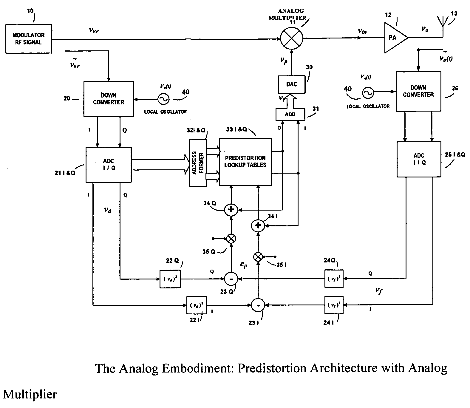
[0007]FIG. 1 illustrates in schematic diagram form a predistortion architecture with analog multiplier in accordance with the present invention.

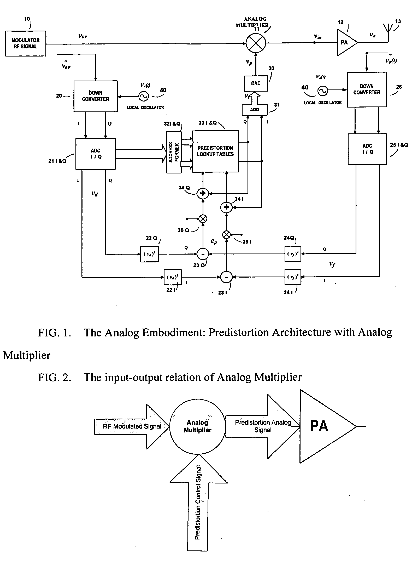
[0008]FIG. 2 illustrates in simplified schematic form the input-output relation of analog multiplier of FIG. 1.

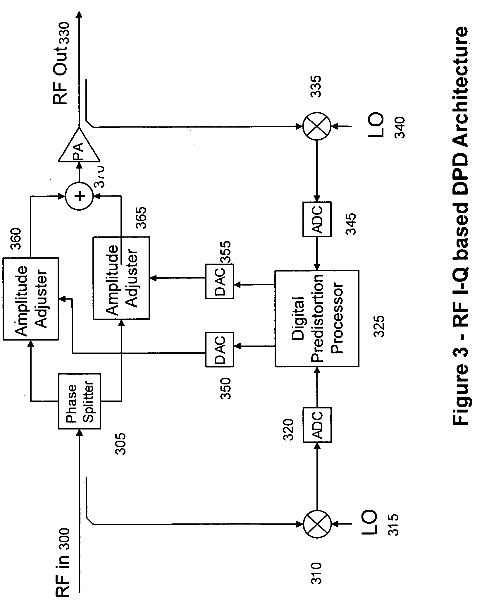
[0009]FIG. 3 illustrates in schematic diagram form an RF I-Q-based DPD Architecture.

[0010]FIG. 4 illustrates in schematic diagram form an RF P-M based DPD Architecture.

[0011]FIGS. 5A and 5B illustrate PA phase compression and cancellation, and PA gain compression and cancellation, respectively, in an RF P-M-based DPD architecture.

DETAILED DESCRIPTION OF THE INVENTION

[0012]On a general level, the analog approach of the present invention approach comprises one or more analog multipliers to combine RF modulated signal vRF(t) and predistortion control signal vp(t) (hereinafter as “RF Modulated Signal” and “Predistort...


PUM


Abstract

An embodiment of the invention is a predistortion approach to linearize a power amplifier by using one or more analog multiplier(s) and a DSP-based processor. For the analog embodiment, the inherent nature of the analog circuitries allows digital predistortion processing structured directly at the RF band, and enables a single power amplifier to support multi-modulation schemes, multi-carriers and multi-channels. As a result, the predistortion architecture is particularly suitable for wireless transmission systems, such as base-stations, repeaters, and indoor signal coverage systems. The wireless system performance can be improved and upgraded just by using the new PA module rather than change or rebuild new subsystem in existing base station. The analog embodiment can also mix and match its analog multipliers with other analog components such as phase splitters, phase shifters, attenuators, filters, couplers, mixers, low-noise amplifiers, buffers, envelope detectors, and etc., to provide additional features.

Description

CROSS REFERENCE TO RELATED APPLICATIONS[0001]This application claims the benefit of U.S. patent application Ser. No. 11 / 799,239, filed Apr. 30, 2007, entitled “High Efficiency Linearization Power Amplifier for Wireless Communication” and its related provisional U.S. patent application Ser. No. 60 / 795,820, filed on Apr. 28, 2006, and further claims the benefit of provisional U.S. Patent Application Ser. No. 60 / 969,127, filed Aug. 30, 2007, having the same title as the present application. Applicant further claims the benefit of U.S. patent application Ser. No. 11 / 262,079, filed Oct. 27, 2005, and its parent application, U.S. patent application Ser. No. 10 / 137,556, filed May 1, 2002, now U.S. Pat. No. 6,985,704. All of the foregoing are hereby incorporated by reference in their entirety for all purposes.BACKGROUND OF THE INVENTION[0002]The current and next-generation wireless communication systems will utilize improved PA efficiency technology for a variety of broadband and multimedia...

Claims


Application Information

Patent Timeline
Patent Type & Authority Applications(United States)
IPC IPC(8): H03F1/32
CPCH03F1/3247H03F3/24H04B1/0475H03F2201/3233Y02B60/50H03F2200/57Y02D30/70H03F3/21H03F3/19H04B2001/0425H03F2200/451H03F2201/3215
Inventor LIU, DONGTAIYANG, DALIANDERSON, JAMES
Owner DALI SYST LTD
Why Eureka
Try Eureka