Electrolytic capacitor

a technology of electrolytic capacitors and capacitors, applied in capacitor electrodes, capacitors, electrical appliances, etc., can solve the problems of aluminum electrolytic capacitor leakage, deterioration of sealing parts, and rise in thesoldering temperature of assembling electronic devices, so as to prevent electrolyte leakage, high capacitance, and high reliability

Inactive Publication Date: 2009-04-02
PANASONIC CORP
View PDF2 Cites 11 Cited by
  • Summary
  • Abstract
  • Description
  • Claims
  • Application Information

AI Technical Summary

Benefits of technology

[0007]The present invention prevents electrolyte leakage and a short circuit caused by dissolution and re-precipitation of copper present in the negative electrode, to provide an electrolytic capacitor with high capacitance and high reliability. The electrolytic capacitor of the present invention includes a capacitor element and an electrolyte solution with which the capacitor element is impregnated. The capacitor element is composed of a positive electrode made of a valve metal; an etched negative electrode containing copper; and a separator disposed between these electrodes. The electrolyte solution contains complex salt of an azole ring compound with copper ions. The azole ring compound in the electrolyte solution forms the complex salt selectively with copper, and the complex salt is stably present in the electrolyte solution, thereby suppressing a short circuit caused by re-precipitation of copper dissolved from the negative electrode. Furthermore, the azole ring compound suppresses electrolyte leakage.

Problems solved by technology

Meanwhile, soldering temperature in assembling electronic devices tends to rise.
High temperatures may cause electrolyte leakage from an aluminum electrolytic capacitor.
Deterioration of a sealing member due to the alkalization is supposed to be the cause of electrolyte leakage.
However, if copper contained in the negative electrode is dissolved into the electrolyte solution and is re-precipitated, a short circuit occurs.
However, this type of aluminum electrolytic capacitor, if aluminum foil containing copper is used for the negative electrode, causes the above-described short circuit particularly in a high-temperature, high-humidity environment.
However, ethylenediaminetetraacetic acid forms complex salt also with aluminum ions dissolved into the electrolyte solution, and thus may insufficiently prevent a short circuit due to dissolution and re-precipitation of copper.

Method used


Image

  • Electrolytic capacitor
  • Electrolytic capacitor
  • Electrolytic capacitor

Examples


example 1

PRACTICAL EXAMPLE 1

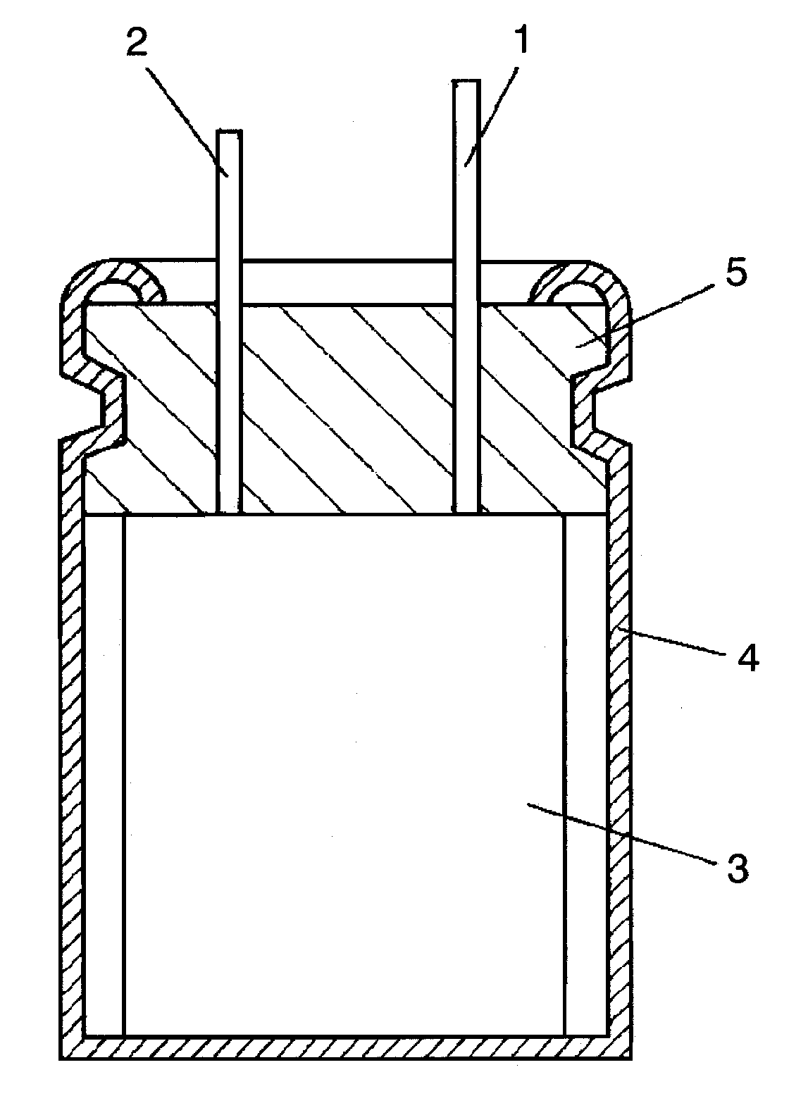
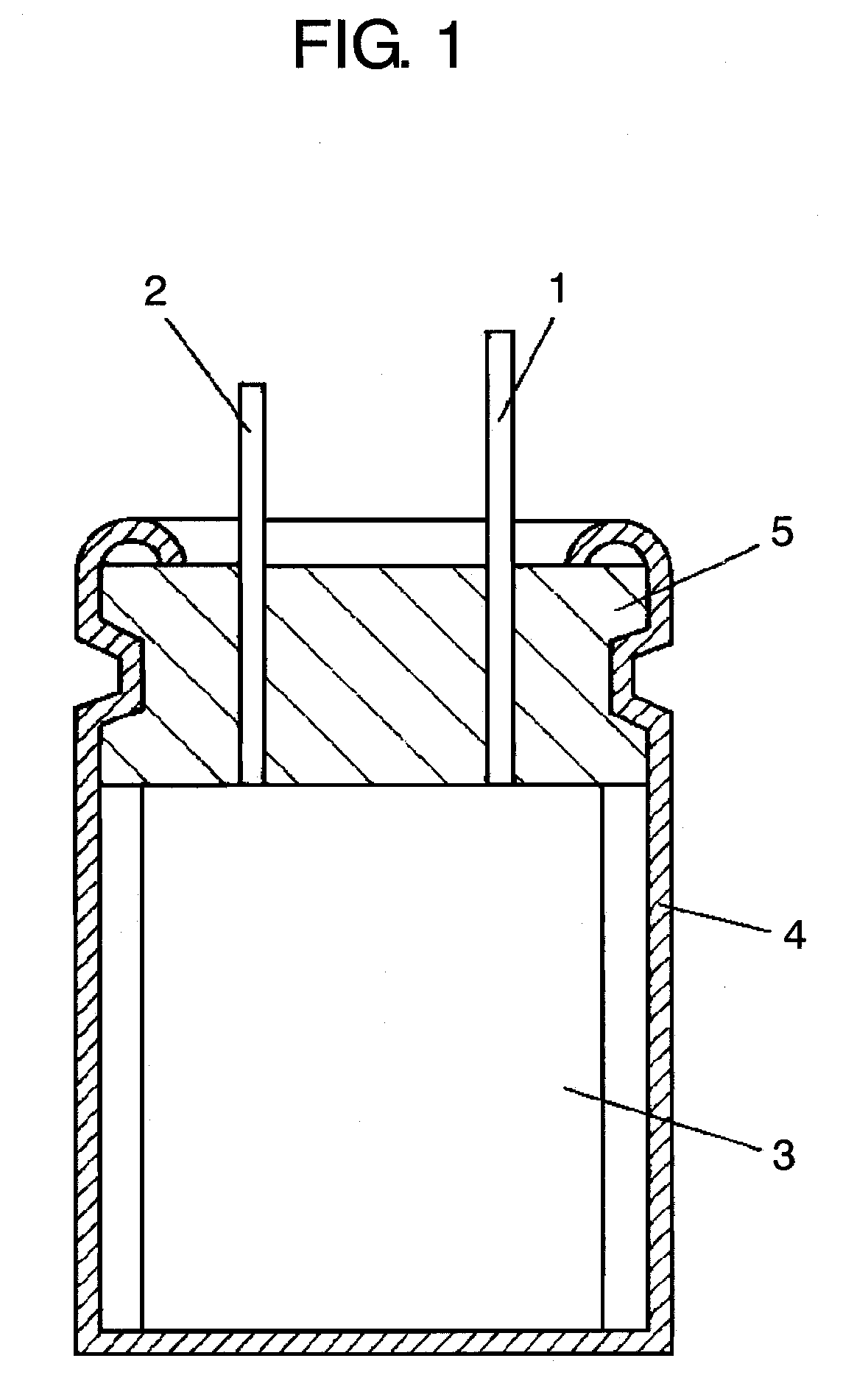
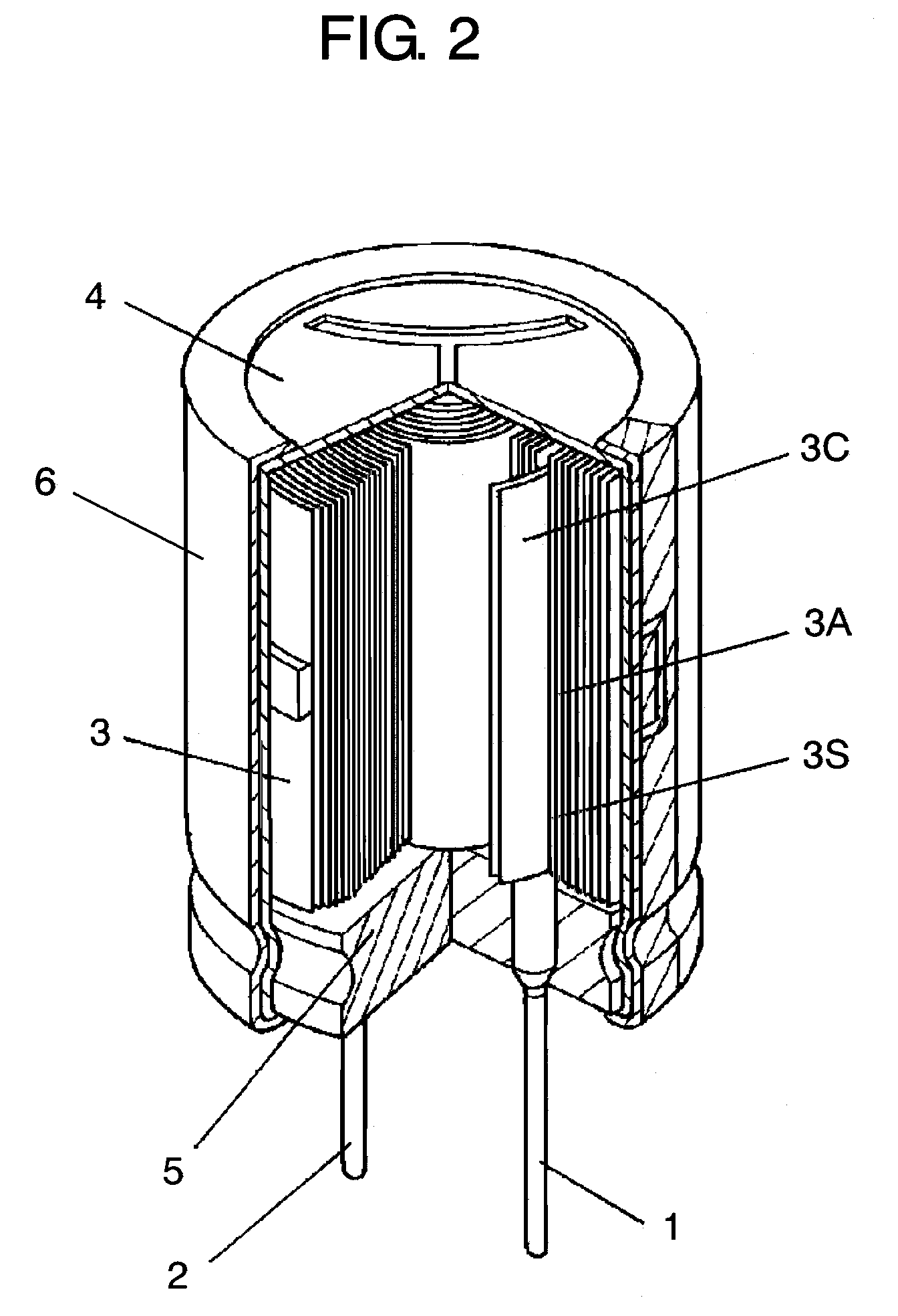
[0030]First, a description is made for how an electrolytic capacitor of sample 1 is produced. After the surface of aluminum foil is roughened by etching, a dielectric oxide film (formation voltage: 15V) is formed by anodization to produce positive electrode 3A. Meanwhile, aluminum foil containing 0.3% of copper in bulk is etched to produce negative electrode 3C. Next, positive electrode 3A and negative electrode 3C are rolled up with separator 3S (a mix-made paper of Manila paper and craft paper, thickness: 50 μm, weight: 40 g / m2) disposed between them to produce capacitor element 3.

[0031]Next, capacitor element 3 is impregnated with an electrolyte solution containing complex salt (0.005 wt %) of an azole ring compound (1-methyl imidazole) with copper ions. Here, the electrolyte solution contains 25 wt % of tetramethylimidazolinium phthalate, 3 wt % of p-nitrobenzoic acid, 1 wt % of monobutyl phosphoester, and the rest of γ-butyrolactone.

[0032]Then, after capacito...

example 2

PRACTICAL EXAMPLE 2

[0037]Samples 7 through 12 in this practical example are produced in the same way as in practical example 1 except that the azole ring compound is benzotriazole, and the content of complex salt of the azole ring compound with copper ions in the electrolyte solution is changed. In samples 13 through 18, the azole ring compound is imidazole; in samples 19 through 24, benzimidazole. After reliability tests are performed for samples 7 through 24 in the same way as in practical example 1, each sample is examined for leakage and a short circuit caused by copper precipitation. The specifications and evaluation results of each sample are shown in tables 2 through 4.

TABLE 2Blending quantity ofLeaks incomplexhigh-temperaturesalt of benzotriazole withandShort circuitcopper ions (wt %)high-humidity testoccurrencesSample 70.00512Sample 80.0100Sample 90.100Sample 101.000Sample 112.000Sample 122.500

TABLE 3Blending quantityLeaks inof complex salt ofhigh-temperatureimidazole with ...

example 3

PRACTICAL EXAMPLE 3

[0040]For samples 25 through 28, 1-methyl imidazole which is an azole ring compound is added when preparing the electrolyte solutions and the content thereof is changed. Capacitor samples are produced in the same way as in practical example 1 except that the capacitor elements are impregnated with the electrolyte solutions respectively and each of the electrolyte solutions is reacted with copper present on the surface of negative electrode 3C by heating in aging process. In the same way, for samples 29 through 32, benzotriazole, which is an azole ring compound, is blended when preparing an electrolyte solution; for samples 33 through 36, imidazole; and for samples 37 through 40, benzimidazole. Here, the electrolyte solution contains 25 wt % of tetramethyl ammonium phthalate, 3 wt % of p-nitrobenzoic acid, 1 wt % of monobutyl phosphoester, and the rest of γ-butyrolactone. After reliability tests are performed for samples 25 through 40 in the same way as in practica...


PUM

PropertyMeasurementUnit
wt %aaaaaaaaaa
wt %aaaaaaaaaa
formation voltageaaaaaaaaaa

Abstract

The electrolytic capacitor includes a capacitor element and an electrolyte solution with which the capacitor element is impregnated. The capacitor element is composed of a positive electrode made of a valve metal, an etched negative electrode containing copper, and a separator disposed therebetween. The electrolyte solution contains complex salt of an azole ring compound with copper ions.

Description

TECHNICAL FIELD[0001]The present invention relates to an electrolytic capacitor used for various types of electronic devices.BACKGROUND ART[0002]The miniaturization and weight reduction of electronic devices are being promoted. Meanwhile, soldering temperature in assembling electronic devices tends to rise. Consequently, aluminum electrolytic capacitors used for electronic devices require miniaturization and greater capacitance with thermal stability against leakage of an electrolyte solution and a short circuit.[0003]High temperatures may cause electrolyte leakage from an aluminum electrolytic capacitor. Aluminum foil for a negative electrode and a lead wire connected to the foil electrochemically react with the electrolyte solution at high temperatures, thereby increasing the amount of hydroxide in the electrolyte solution near the lead wire. Deterioration of a sealing member due to the alkalization is supposed to be the cause of electrolyte leakage.[0004]Meanwhile, miniaturizatio...

Claims


Application Information

Patent Timeline
Patent Type & Authority Applications(United States)
IPC IPC(8): H01G9/035
CPCH01G9/035H01G9/145H01G9/045H01G9/04
Inventor TSUBAKI, MASAMINAGARA, HISAOHONDA, KAZUMITSU
Owner PANASONIC CORP
Why Eureka
Try Eureka