Precision laser machining apparatus

a laser machining and precision technology, applied in the direction of optical elements, instruments, manufacturing tools, etc., can solve the problems of less utility in fine machining applications, less precision over a large field, and more optically and mechanically complex approaches, etc., to achieve excellent precision and repeatability.

Inactive Publication Date: 2009-04-16
MICHAEL J SCAGGS
View PDF11 Cites 8 Cited by
  • Summary
  • Abstract
  • Description
  • Claims
  • Application Information

AI Technical Summary

Benefits of technology

[0028]A closely related object is to manipulate the beam laser in such a way as to remove a wide variety o

Problems solved by technology

They have less utility in fine machining applications, in particular drilling precision holes and features below 250 microns, because their positional accuracy is limited below such threshold.
Non-galvo-based approaches are limited to circular features and tend to be more optically and mechanically complex.
Nevertheless, they lack the “localized” precision for finite features over a large field.
It is very difficult to form precision holes or any arc feature below 200 microns in diameter.
Moreover, the angular resolution of the galvo motors is a further hindrance to the problem of small features and the attainment of high repeatability.
The known systems are also subject to limited angular resolution and thermal drift which further hinders the ability of the device to machine precision features over a long period of time, e.g., a single production shift in manufacturing.
Rotating, offset wedge pairs allow good precision below 250 microns, but they only permit circular features

Method used


Image

  • Precision laser machining apparatus
  • Precision laser machining apparatus

Examples


Embodiment Construction

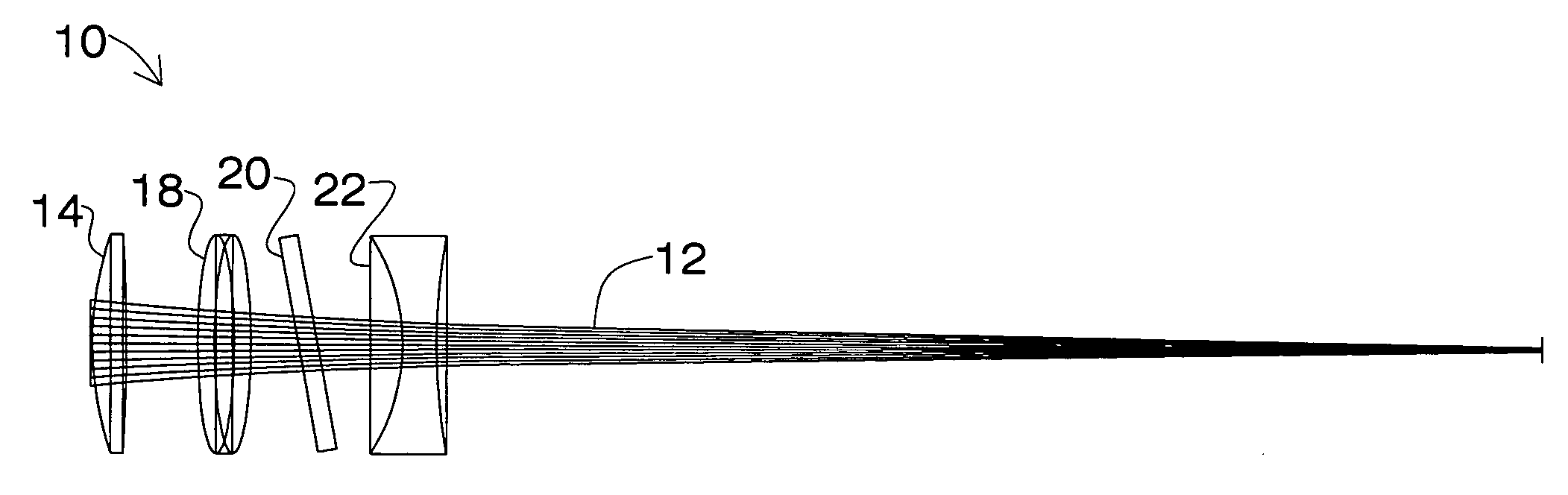
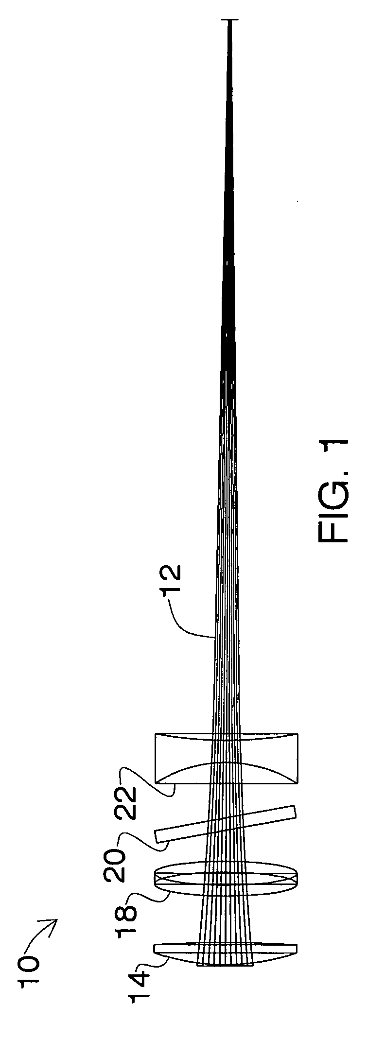
[0031]Referring now to the FIGURE, there it will be seen that an illustrative embodiment of the invention is denoted as a whole by the reference numeral 10.

[0032]Incoming laser beam 12 passes through simple, positive lens 14 and then through a pair of plane, parallel windows 18, 20. Each of said plane, parallel windows is mounted to a galvanometer motor and is positioned orthogonally to one another.

[0033]Simple, positive lens 14 and negative lens 22 are optimized with a computer optical design program to minimize aberrations (spherical, coma and astigmatism) of the system. There are many commercially available programs to perform the optimization, such as Zemax®, OSLO®, CODE V®, and Beam 3®, to name a few. All have utility in optical design work and perform essentially the same function.

[0034]As is well known, the variables that can be optimized in a computer optical design program are the radius of curvature of each lens, type of glass, glass thickness and spacing between lenses. A...


PUM

PropertyMeasurementUnit
Lengthaaaaaaaaaa
Sizeaaaaaaaaaa

Abstract

A focused laser beam having an optical axis passes sequentially through a simple, positive lens, a pair of plane, parallel windows, and a second, simple, negative lens. Each of the plane, parallel windows are mounted to a galvanometer motor and positioned orthogonally to one another. The focused laser beam is therefore displaced in a controlled manner from the optical axis to enable laser machining of very precise geometric features over a large processing window. A field size of one thousand microns is achieved.

Description

CROSS-REFERENCE TO RELATED DISCLOSURES[0001]This disclosure is a continuation-in-part application claiming the benefit of the filing date of pending U.S. patent application entitled: “Precision Laser Machining Apparatus,” by the same inventors, filed Feb. 14, 2007, bearing Ser. No. 11 / 674,730.BACKGROUND OF THE INVENTION[0002]1. Field of the Invention[0003]This invention relates to optical scanning devices used for laser machining. More particularly, it relates to a high precision laser hole drilling and controlled material removal of geometries of less than 500 microns.[0004]2. Description of the Prior Art[0005]Galvanometer scanners have been used for nearly three (3) decades for laser material processing. They are most commonly used for laser marking. They have less utility in fine machining applications, in particular drilling precision holes and features below 250 microns, because their positional accuracy is limited below such threshold. Non-galvo-based approaches are limited to...

Claims


Application Information

Patent Timeline
IPC IPC(8): B23K26/38
CPCG02B26/105G02B26/101
Inventor SCAGGS, MICHAEL J.SCHOELZEL, THOMAS
Owner MICHAEL J SCAGGS
Why Eureka
Try Eureka