Excimer lamps

a technology of excimer lamps and lampshades, which is applied in the direction of instruments, discharge tubes, luminescnet screens, etc., can solve the problems of uneven illumination in the axial direction of the discharge vessel, and achieve the effect of efficient reflection and diffusion

Active Publication Date: 2009-04-16
USHIO DENKI KK
View PDF25 Cites 1 Cited by
  • Summary
  • Abstract
  • Description
  • Claims
  • Application Information

AI Technical Summary

Benefits of technology

[0013]In the excimer lamp according to the present invention, particle boundaries do not disappear by lighting for an extended period of time because an ultraviolet reflection film is constituted of silica particles and alumina particles, and the silica particles have a specified mean particle diameter relative to the mean particle diameter of the alumina particles. Vacuum ultraviolet radiation can therefore be reflected and diffused efficiently while maintaining the initial reflectivity, and mass difference between the silica particles and the alumina particles caused by a difference in specific gravity can be maintained within a specified range, which allows equalizing the flow properties of the silica particles and alumina particles in a liquid dispersion prepared at the time of forming an ultraviolet reflection film. As a result, the silica particles and alumina particles are evenly dispersed in the ultraviolet reflection film, which allows a uniform illuminance in the axial direction of the discharge vessel to be achieved.

Problems solved by technology

However, it was found that there was a problem in excimer lamps equipped with the aforementioned ultraviolet reflection film that the illuminance becomes uneven in the axial direction of the discharge vessel.

Method used


Image

  • Excimer lamps
  • Excimer lamps
  • Excimer lamps

Examples


embodiment 1

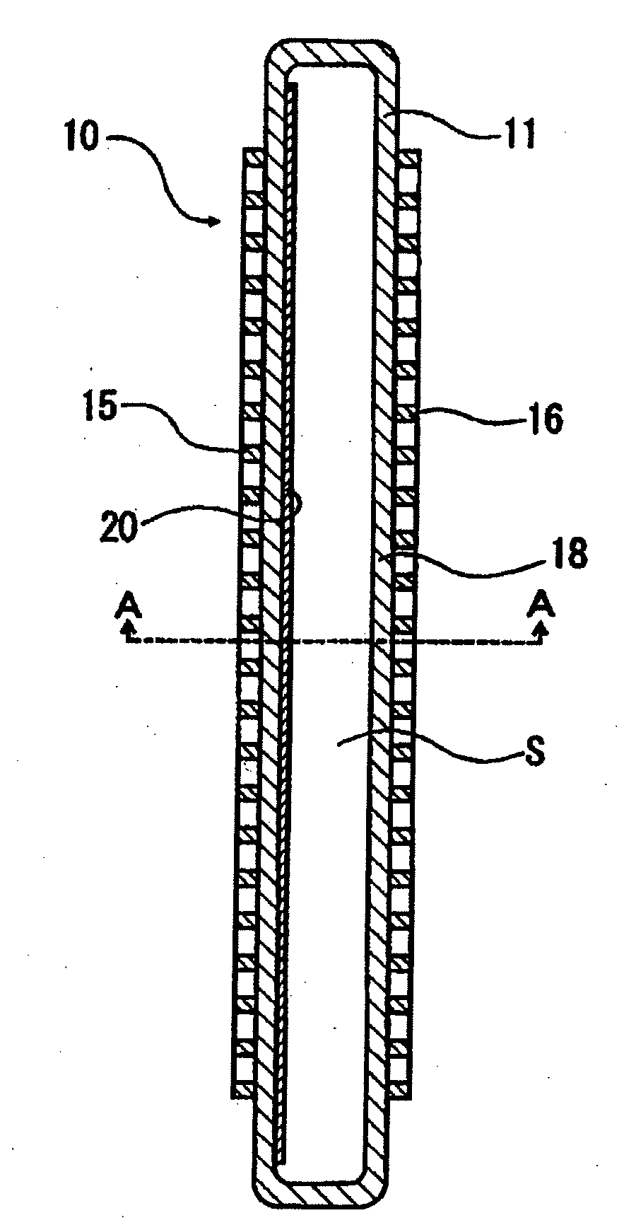
[0053]In accordance with the configuration as shown in FIG. 1(a) &1(b), 8 types of excimer lamps were made having the same configuration except that the ratio of the mean particle diameter D1 of silica particles relative to the mean particle diameter D2 of alumina particles (D1 / D2) was different in the ultraviolet reflection films as shown in Table 1 below. A description of the basic configuration of the excimer lamps is given below.

(Configuration of Excimer Lamps)

[0054]The dimension of the discharge vessel was 10×40×900 mm. The thickness was 3 mm.

[0055]The discharge gas filled in the discharge vessel was xenon gas. The amount was 50 kPa.

[0056]The size of the high voltage supply electrode and grounded electrode was 30 mm×800 mm.

[0057]The emission length of the excimer lamp was 800 mm.

[0058]In the ultraviolet reflection film, silica particles having the mean particle diameter account for 50%. Alumina particles having the mean particle diameter also account for 50%.

[0059]The size of s...

embodiment 2

[0063]Eight types of excimer lamps having the same configuration as used in Embodiment 1, except that the emission length was 1600 nm and that 1he ratio of 1he mean particle diameter D1 of silica particles to the mean particle diameter D2 of alumina particles (D1 / D2) was different in the ultraviolet reflection film as shown in Table 2 below. An experiment was conducted in the same manner as in Embodiment 1 to find the relative illuminance of each excimer lamp. Table 2 shows the results.

TABLE 2MeanSilica particlesAlumina particlesparticleRange ofMean particleRange ofMean particlediameterRelativeparticle sizediameter D1particle sizediameter D2ratio D1 / illuminance[μm][μm][μm][μm]D2[%]Excimer lamp 9 0.1 to 103.00.1 to 10.310.083.6Excimer lamp0.1 to 81.50.1 to 10.35.0083.510Excimer lamp0.1 to 51.00.1 to 10.33.3381.811Excimer lamp0.1 to 20.50.1 to 10.31.6780.612Excimer lamp0.1 to 10.30.1 to 10.31.0079.313Excimer lamp 0.05 to 0.50.20.1 to 10.30.6772.114Excimer lamp 0.01 to 0.20.10.1 to 10....

embodiment 3

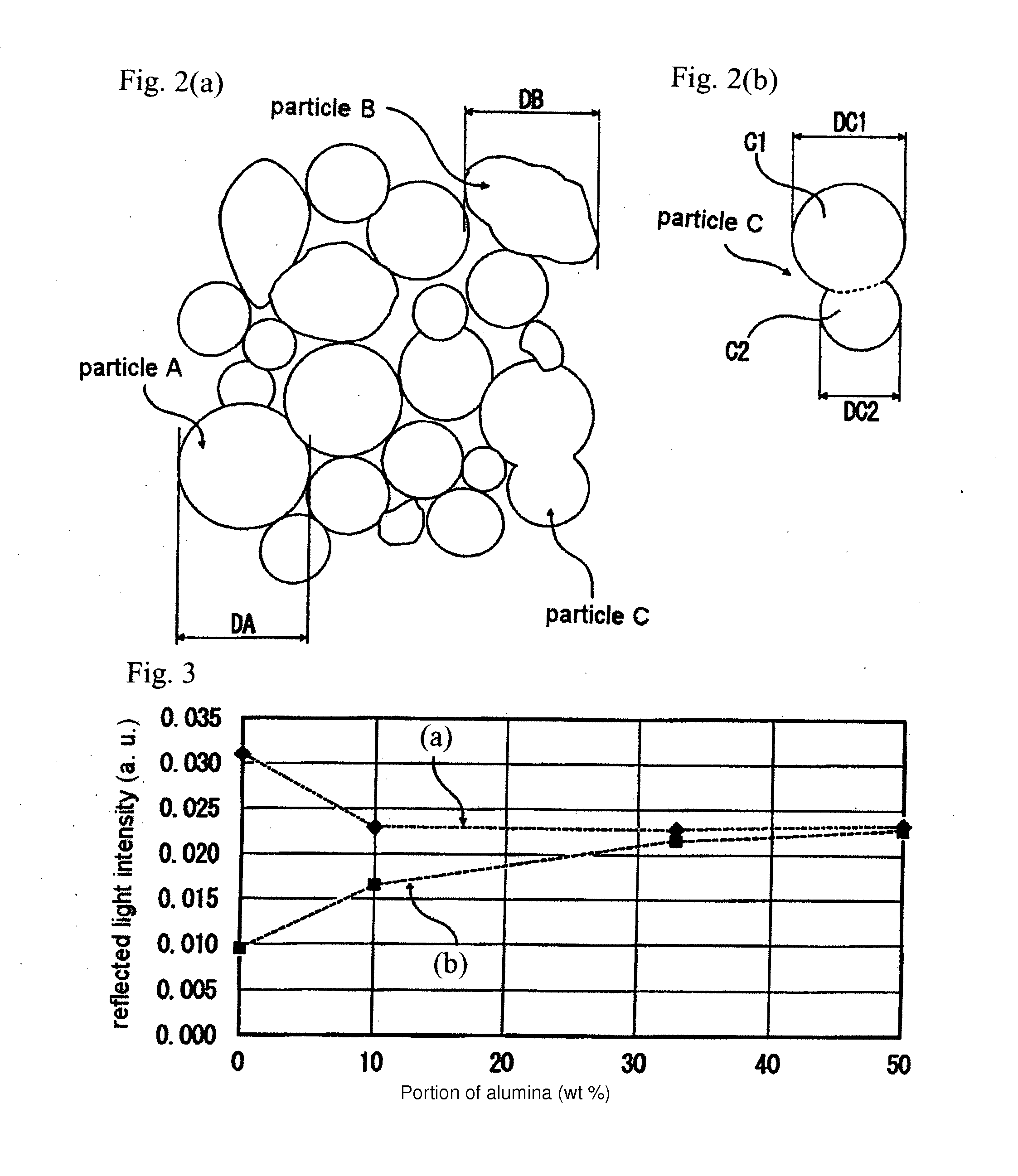
[0065]Four types of test pieces were produced by forming ultraviolet reflection films of 30 μm on a plate-shaped substrate made of silica glass, wherein the ultraviolet reflection films were made of silica particles and alumina particles, wherein the mean particle diameter (D1) of silica particles was 0.3 μm and the mean particle diameter (D2) of alumina particles was 0.3 μm (D1 / D2=1.00), and wherein the content rates of alumina particles were, 0 wt %, 10 wt %. 33 wt % and 50 wt %.

[0066]Then, the intensity of reflected light with a wavelength of 170 nm was measured for each test piece by heating an ultraviolet reflection film at 1000° C. (as shown by a line (a) in FIG. 3) and by heating it at 1,300° C. (as shown by a line (b) in FIG. 3). FIG. 3 shows the results. Here, 1000° C., which was the heating temperature of the ultraviolet reflection films, corresponded to the baking temperature at the time of forming the ultraviolet reflection films, and 130° C. corresponded to the heating ...


PUM


Abstract

To avoid a decline in the reflectivity of an ultraviolet reflection film caused by lighting for an extended period of time and providing a uniform illuminance an excimer lamp has a silica glass discharge vessel with electrodes on opposite sides of the discharge vessel, wherein excimer discharge is generated in the discharge space of the discharge vessel, wherein an ultraviolet reflection film made of silica particles and alumina particles is formed on a surface exposed to the discharge space and wherein the mean particle diameter of silica particles is at least 0.67 times as large as the mean particle diameter of the alumina particles. The alumina particles in the ultraviolet reflection film preferably constitute at least 5 wt % and more preferably at least 10 wt % of the sum of silica particles and alumina particles.

Description

BACKGROUND OF THE INVENTION [0001]1. Field of Invention[0002]The present invention relates to an excimer lamp comprising a discharge vessel made of silica glass having a discharge space, wherein a pair of electrodes is provided on both sides of the silica glass vessel and wherein excimer discharge is generated inside the discharge vessel.[0003]2. Description of Related Art[0004]Various technologies have been developed and put into practical use recently for treating an article made of metal, glass or other materials by means of the action of vacuum ultraviolet radiation with a wavelength of at most 200 nm and ozone generated thereby by radiating the vacuum ultraviolet radiation onto the article to be treated, which includes a cleaning treatment technology for removing organic impurities adhering to the surface of the article and an oxide film formation treatment technology for forming an oxide film on the surface of the article to be treated.[0005]As an example, a device for emittin...

Claims


Application Information

Patent Timeline
Patent Type & Authority Applications(United States)
IPC IPC(8): H01K1/28
CPCH01J65/00H01J61/35
Inventor FUJISAWA, SHIGEKIMORIMOTO, YUKIHIRO
Owner USHIO DENKI KK
Why Eureka
Try Eureka