
Manufacturing method for far-infrared irradiating substrate

a manufacturing method and technology of far-infrared ceramic powder, applied in the direction of vacuum evaporation coating, solid-state diffusion coating, coating, etc., can solve the problem that the far-infrared ceramic powder cannot be completely buried, and the danger to the human body, etc., to achieve the effect of evaporation efficiency

Inactive Publication Date: 2009-04-16
NAT APPLIED RES LAB +1
View PDF4 Cites 3 Cited by
  • Summary
  • Abstract
  • Description
  • Claims
  • Application Information

AI Technical Summary

Benefits of technology

[0020]Preferably, the manufacturing method further comprises a step of performing an ion beam assisted deposition by means of the ion source, which contributes to the evaporating efficiency.

Problems solved by technology

However, some of the current commercial far-infrared irradiating products still contain excess rare elements, wherein the radioactive irradiation emitted therefrom might bring about the potential dangerous threat to human body.
However, the maximal content of far-infrared irradiating material in the mentioned fibrous filaments is approximately 5% that cannot provide the sufficient amount of far-infrared ray since the additives of the fibrous macromolecules might lower down the fibrous strength and wear the spinning nozzle.
Besides, the factors of the larger diameter of far-infrared irradiating ceramic powders and the thinner fibrous filaments might result in that the far-infrared ceramic powders cannot completely buried within the filaments.

Method used


Image

  • Manufacturing method for far-infrared irradiating substrate
  • Manufacturing method for far-infrared irradiating substrate
  • Manufacturing method for far-infrared irradiating substrate

Examples


Embodiment Construction

[0028]The present invention will now be described more specifically with reference to the following embodiments. It is to be noted that the following descriptions of preferred embodiments of this invention are presented herein for the purposes of illustration and description only; it is not intended to be exhaustive or to be limited to the precise form disclosed.

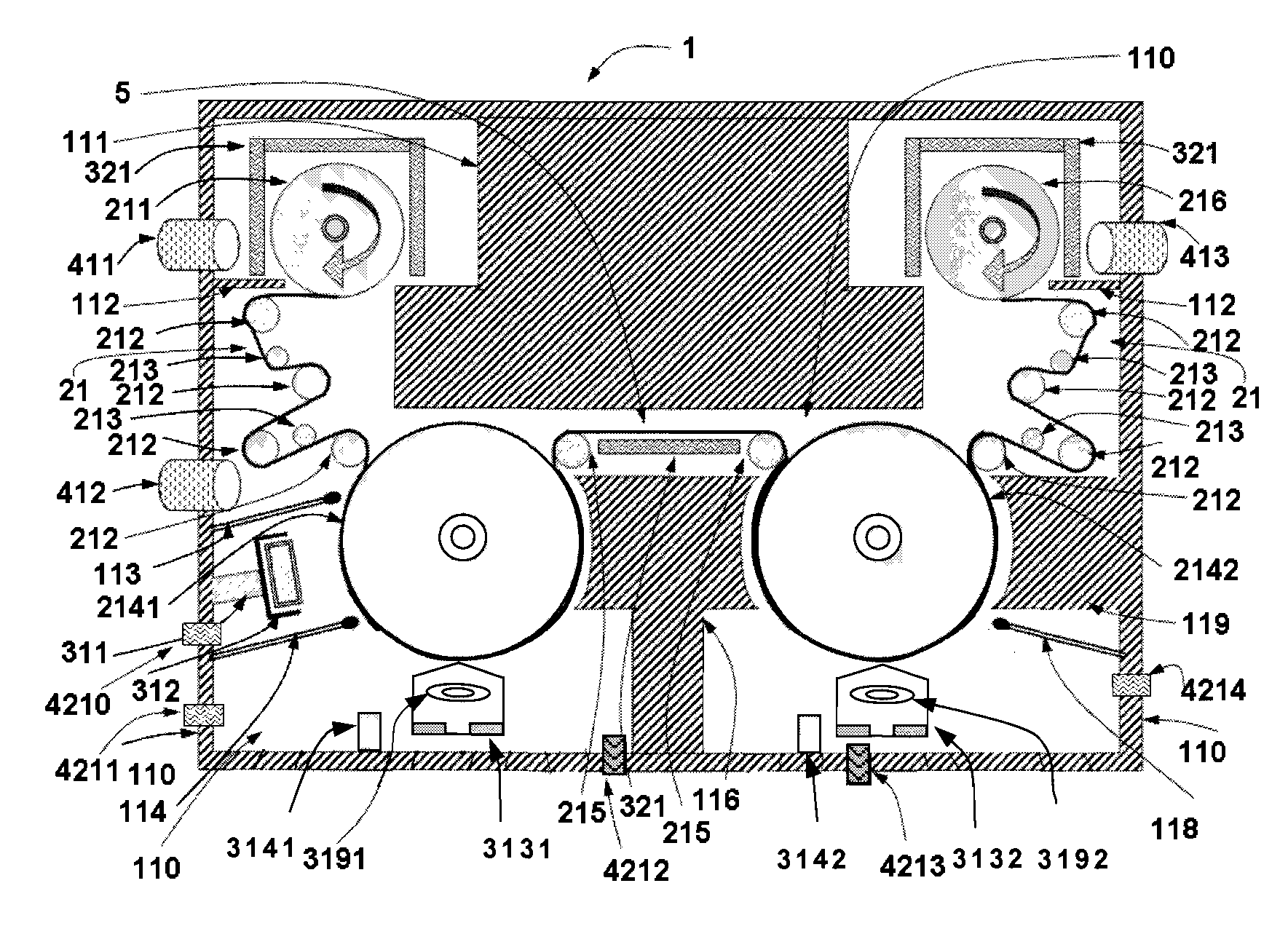
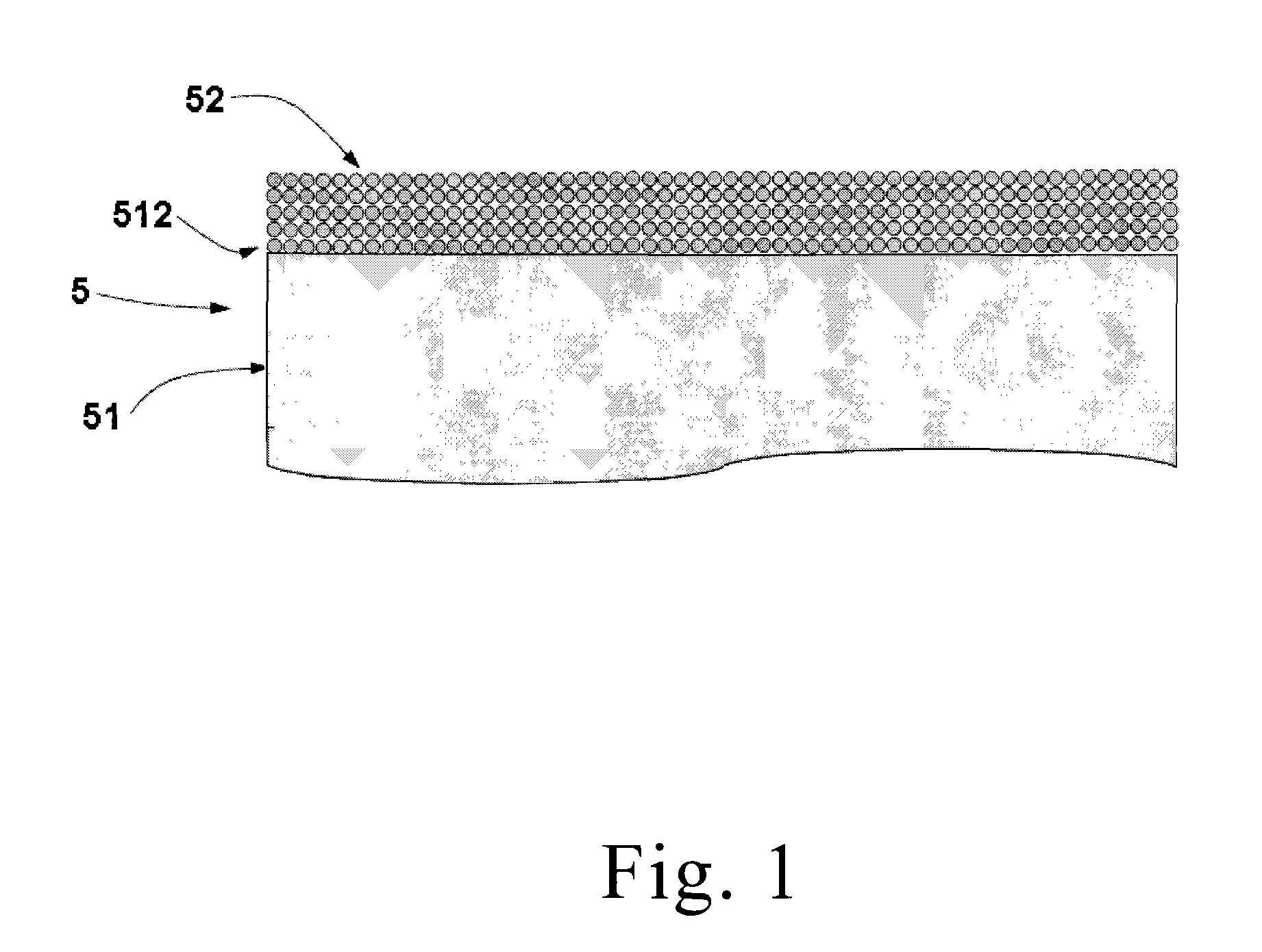
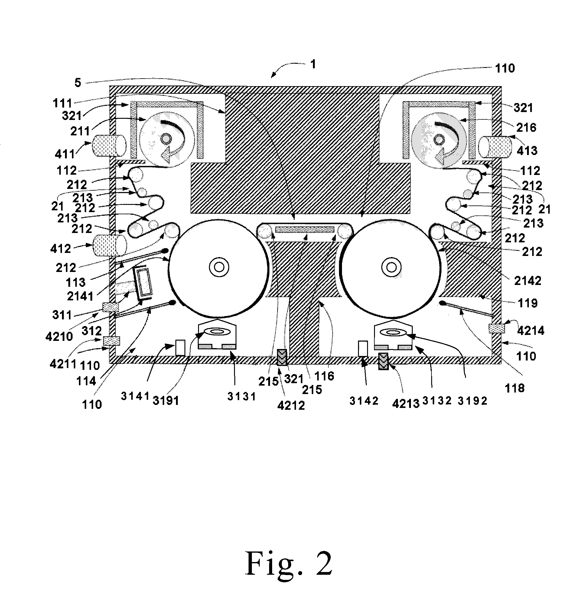
[0029]Please refer to FIG. 1, which shows a lateral diagram of the far-infrared irradiating substrate according to a preferred embodiment of the present invention. A far-infrared irradiating substrate 5 of the present invention includes a substrate 51 and a far-infrared irradiating thin film 52 with a thickness ranged from 10 nanometer to 10 micrometer, wherein the far-infrared irradiating thin film 52 is formed on a surface 512 of the substrate 51 that predetermined to be treated by an ion source. The mentioned far-infrared irradiating thin film 52 is formed by several layers of far-infrared irradiating particles piling up ...


PUM

PropertyMeasurementUnit
Temperatureaaaaaaaaaa
Lengthaaaaaaaaaa
Thicknessaaaaaaaaaa

Abstract

A manufacturing method for a far-infrared irradiating substrate is provided. The manufacturing method comprises steps of providing a substrate, providing a far-infrared irradiating material and evaporating the far-infrared irradiating material to form a thin film onto the substrate. The far-infrared irradiating substrate provided by the present invention not only has a high emission coefficient of far-infrared ray, but also do not cause a potential exposure of an ionizing radiation.

Description

FIELD OF THE INVENTION[0001]The present invention relates to a method for manufacturing a far-infrared irradiating substrate, and more particularly to a method for manufacturing a far-infrared irradiating substrate by means of an evaporation.BACKGROUND OF THE INVENTION[0002]Far-infrared radiation is a form of electromagnetic radiation having a wavelength range of 3 to 1000 micrometers. Far-infrared rays (FIR) are part of the sunlight spectrum which is invisible to the naked eye. It also known as biogenetic rays (between 6 to 14 microns). Biogenetics rays have been proven by scientists to promote the growth and health of living cells especially in plants, animals and human beings. Far infrared radiation may help improve blood circulation, strengthen the cardiovascular system, relax muscles and increase flexibility, relieve pain, deep cleanse skin, remove toxins and mineral waste, burn calories and controls weight, improve the immune system, reduce stress and fatigue, eliminate waste ...

Claims


Application Information

Patent Timeline
IPC IPC(8): C23C14/48C23C16/44
CPCC23C14/562C23C14/022
Inventor CHIU, PO-KAICHO, WEN-HAOPAN, HAN-CHANGLIN, YUNG-SHENGLEUNG, TING-KAI
Owner NAT APPLIED RES LAB
Learn More