Nanocrater catalyst in metal nanoparticles and method for preparing the same

a metal nanoparticle and catalyst technology, applied in the field of nanoparticle catalysts in metal nanoparticles, can solve the problems of not being commercially available, not significantly progressing in the study and development of metal nanoparticles, and not being able to achieve the desired structure of metal nanoparticles, etc., to achieve a simple and economical process

Active Publication Date: 2009-04-16
KOREA ADVANCED INST OF SCI & TECH
View PDF0 Cites 54 Cited by
  • Summary
  • Abstract
  • Description
  • Claims
  • Application Information

AI Technical Summary

Benefits of technology

[0014]Another objective of the present invention is to provided a method for preparing a nanocrat

Problems solved by technology

However, there are still serious problems or difficulties in preparation of metal nanoparticles with desired structure and characteristics and, in the present circumstances, studies and developments of the metal nanoparticles have not considerably progressed.
However, such methods have drawbacks in that these are not commerc

Method used


Image

  • Nanocrater catalyst in metal nanoparticles and method for preparing the same
  • Nanocrater catalyst in metal nanoparticles and method for preparing the same
  • Nanocrater catalyst in metal nanoparticles and method for preparing the same

Examples


example 1

Preparation of Nanocrater Iron Catalyst

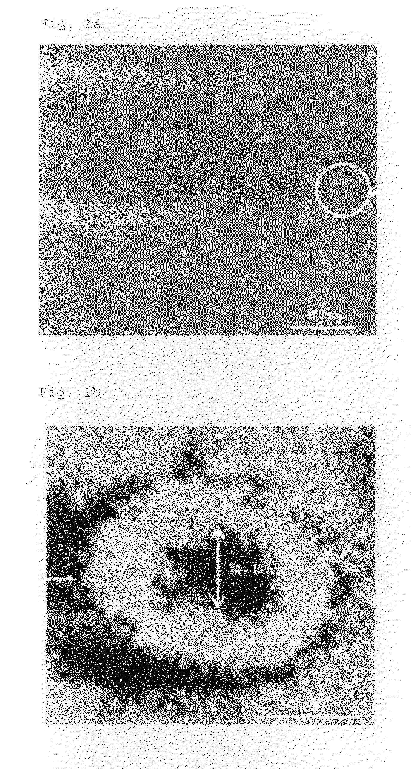
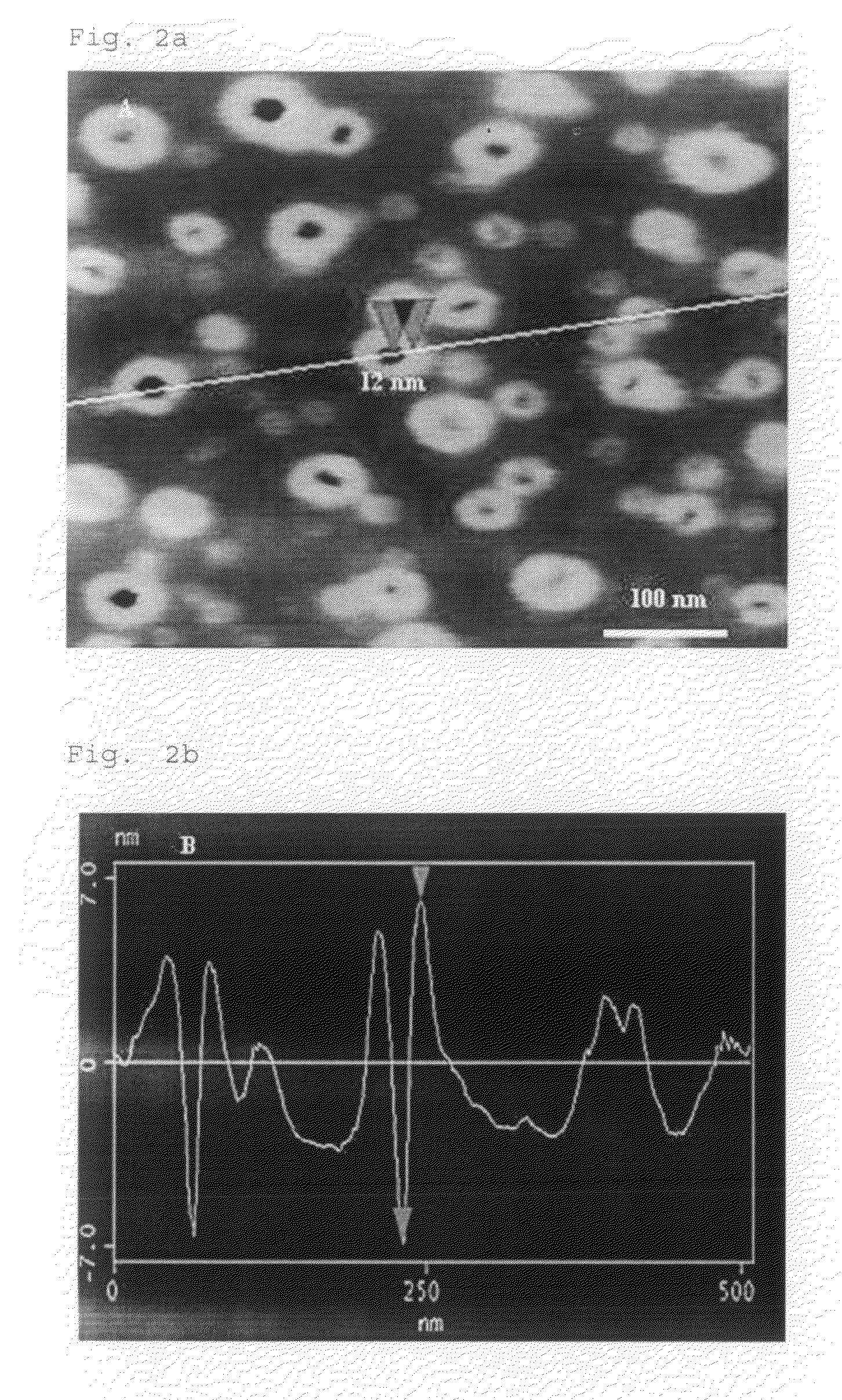
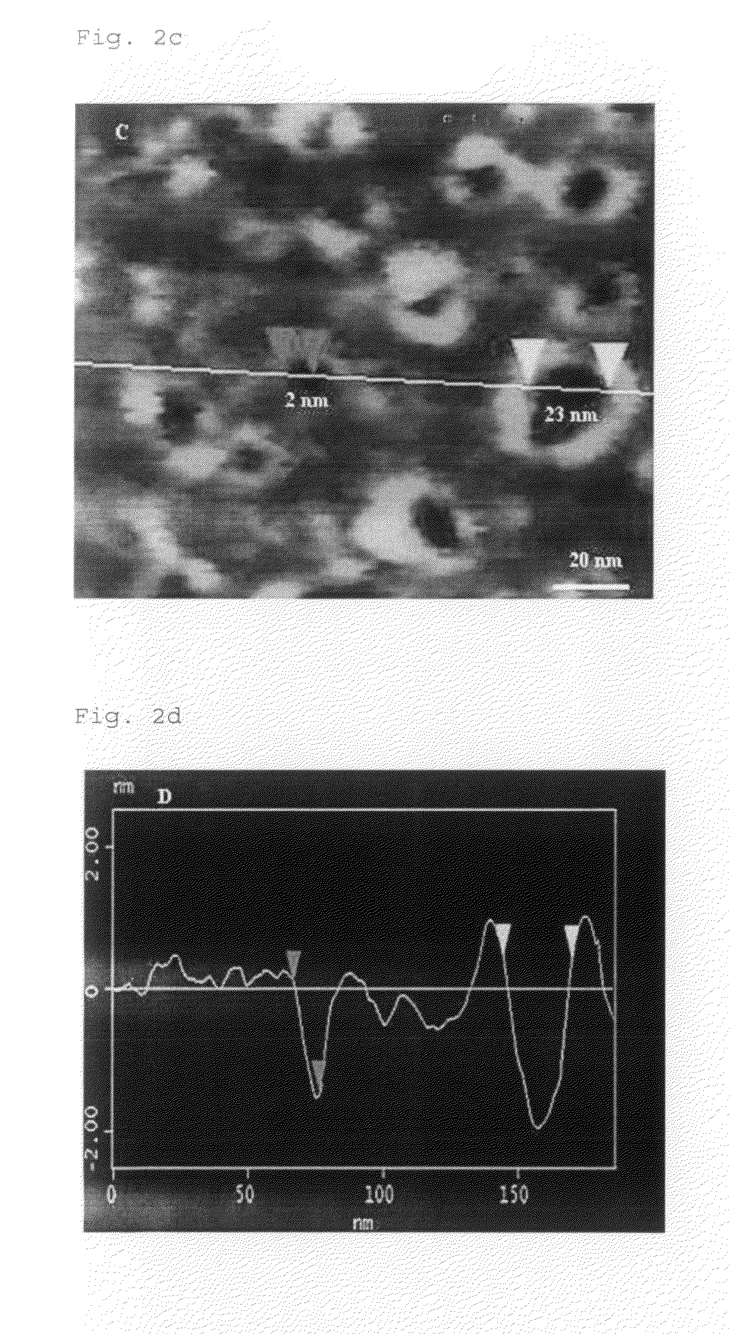
[0046]For preparation of a nanocrater iron catalyst, first of all, an iron film with a thickness of about 10 nm was vapor-deposited on a silicon substrate at 200° C. by means of a sputtering process. Then, the deposited substrate was plasma etched using 100 sccm of nitrogen gas with a plasma power of 600 W at 800° C. for 1 minute.

[0047]Among the above processes, the metal films separated and etched in the range of nano units by the plasma treatment process produced a plurality of vacancies and dislocations in inherent structure of the metal nanoparticles. Next, after preparing an iodine-containing nitric acid / ethanol solution which was a solution mixture of 100 Ml of ethanol and 20 Ml of nitric acid containing 3.5 g of iodine (I), the metal nanoparticles with vacancies and dislocations in structure thereof underwent the etching process in the prepared solution for 3 hours. As a result, a nanocrater iron catalyst with a nanocrater form of hole s...

example 2

Preparation of Nanocrater Cobalt Catalyst

[0048]For preparation of a nanocrater iron catalyst, first of all, a cobalt film with thickness of about 10 nm was vapor-deposited on a silicon substrate at 200° C. by means of a sputtering process. Then, the deposited substrate was plasma etched using 90 sccm of nitrogen gas with a plasma power of 700 W at 700° C. for 1 minute.

[0049]Among the above processes, the metal films separated and etched in the range of nano units by the plasma process produced a plurality of vacancies and dislocations in inherent structure of the metal nanoparticles. Next, after preparing an iodine-containing nitric acid / ethanol solution which was a solution mixture of 100 Ml of ethanol and 20 Ml of nitric acid containing 3.5 g of iodine (I), the metal nanoparticles with vacancy and dislocation in structure thereof underwent the etching process in the prepared solution for 3 hours. As a result, a nanocrater cobalt catalyst with a nanocrater form of hole structure at...

example 3

Fabrication and Growth of Carbon Nanotubes by Using Nanocrater Iron Catalyst

[0050]By means of plasma chemical vapor-deposition using the nanocrater iron catalyst prepared in Example 1, carbon nanotubes were fabricated. More particularly, the carbon nanotubes were produced using the nanocrater iron catalyst together with 85 sccm of nitrogen gas and 15 sccm of methane gas for 8 minutes in desired conditions of plasma power of 700 W at 900° C. under 23 Torr of pressure.


PUM

PropertyMeasurementUnit
Fractionaaaaaaaaaa
Percent by massaaaaaaaaaa
Thicknessaaaaaaaaaa

Abstract

Disclosed are a nanocrater catalyst in metal nanoparticles with a nanocrater form of hole structure in center of the catalyst which is useful for manufacturing nano-sized materials and/or articles with desired structure and characteristics, a preparation method thereof including a plasma etching and chemical etching process (“PTCE process”), and nano-sized materials and/or articles manufactured by using the nanocrater catalyst in metal nanoparticles.

Description

[0001]This application claims priority to Korean Patent Application No. 10-2007-0102100, filed on Oct. 10, 2007, in the Korean Intellectual Property Office, the entire contents of which are hereby incorporated by reference.BACKGROUND OF THE INVENTION[0002]1. Field of the Invention[0003]The present invention relates to nanocrater catalyst in metal nanoparticles and their preparation methods, more particularly, to a nanocrater catalyst in metal nanoparticles with a nanocrater form of hole structure at the center of the catalyst, a preparation method thereof including a plasma etching and chemical etching process (“PTCE process”) and nano-sized materials and / or articles manufactured by using the nanocrater catalyst in metal nanoparticles.[0004]2. Description of the Related Art[0005]Nano-sized metal particles have electric, optic and / or magnetic properties different from those of bulk metal materials and have recently received increased attention in a wide range of applications.[0006]Me...

Claims


Application Information

Patent Timeline
IPC IPC(8): B22F5/10C23F1/04
CPCB01J21/185B01J23/74B01J35/10B01J37/0238B01J37/349Y10T428/12014B82Y40/00C01B31/0233C01B31/0293Y10S977/775Y10S977/777B82Y30/00C01B32/162C01B32/18B01J23/745B82B3/00B01J37/34B01J23/75
Inventor KANG, JEUNG-KUSAJI, AUGUSTINELEE, JUNG-WOOSHIN, WEON-HOHAN, KYU-SUNGCHOI, JUNG-HOON
Owner KOREA ADVANCED INST OF SCI & TECH
Why Eureka
Try Eureka