Audio Power Conversion System

a power conversion and audio technology, applied in the direction of ac-dc conversion, amplifiers, electric variable regulation, etc., can solve the problems of increasing distortion, needing a dual rail supply, and affecting the performance of the amplifier

Active Publication Date: 2009-04-23
BANG & OLUFSEN ICEPOWER
View PDF10 Cites 24 Cited by
  • Summary
  • Abstract
  • Description
  • Claims
  • Application Information

AI Technical Summary

Benefits of technology

[0040]Such switching will effectively mirror the two supply rails onto each other. This has two distinct advantages. Firstly, any variation in the two rail voltages is equalized (pump canceling). Secondly, this circuit effectively utilizes the capacity of both rails which means that dynamic power delivered from the rail capacitors becomes equal to that utilized in a single rail supply with the same amount of capacity.
[0041]The switching means can comprise controlled switches, such as MOSFETs. The simple drive pattern of the MOSFETs also enables a simple way to implement soft-switching techniques of the transistors. The circuit can then comprise a switch control system for providing two pulse trains with equally spaced, non-overlapping pulses of equal length, for controlling the controlled switches

Problems solved by technology

The drawback of the half-bridge class D topology is the need for a dual rail supply and the fact that this topology will pump current back to the opposite supply rail from where the power is being drained.
Also performance of the amplifier will be affected by the rail pumping especially non-feedback class D amplifiers where the asymmetrical rail perturbation will be modulated directly onto the audio signal dramatically increasing the distortion.
These drawbacks can be summarized as:Excessive use of rail capacitors =>higher cost and larger physical sizeHigher voltage-rated devices in terms of rail Capacitors and amplifier MOSFETs =>higher cost and larger physical sizeUnacceptable audio performance for non-feedback class D amplifiers and degraded audio performance for feedback class D amplifiers =>reduced product value
1) The circuit redistributes the pumping energy in a 2 step operation. In the first step energy is stored in an inductor to be released in the second step.
2) The circuit uses two separate control systems.
3) The circuit will only limit the rail pumping—not cancel it.
4) The circuit will not help utilizing rail capacitance on both rails.
5) The circuit is based on a “buck-boost” topology renowned for its poor conversion efficiency.

Method used


Image

  • Audio Power Conversion System
  • Audio Power Conversion System
  • Audio Power Conversion System

Examples


Embodiment Construction

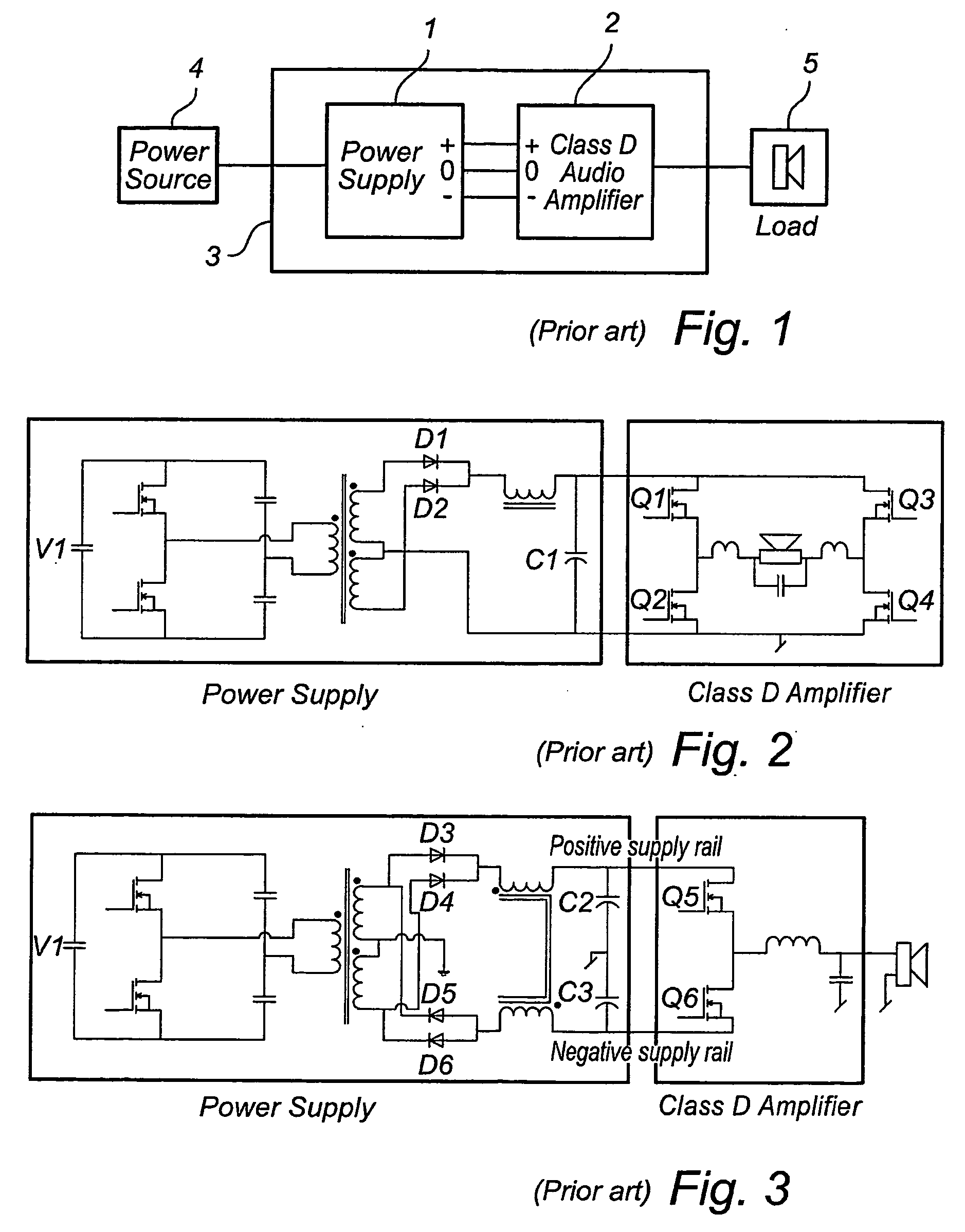
[0060]A block schematic of an audio power conversion system is shown in FIG. 1. The power supply (1) can be a switched mode supply or a linear type. Depending on the type of amplifier the supply is sourcing the output will be either a single rail or a dual rail supply. The class D amplifier (2) will typically be a half-bridge (single-ended) or a full-bridge topology. The number of channels in (2) can vary from 1 to multiple channels. The load (3) is typically an electro dynamic loudspeaker but can be any kind of transducer transforming the electrical signal from the amplifier to an acoustic signal. The power source (4) can be an AC-source, e.g. the utility net, or it could be a battery (e.g. automotive, portable equipment). The output of the power source (4) is a DC-voltage (or almost) which means that in case of an AC-source input, means to rectify and stabilize the voltage is included in (4). The electrical part of the audio power conversion system is defined as (3).

[0061]Given th...


PUM


Abstract

An audio power conversion system includes a power supply having a positive supply rail and a negative supply rail for supplying power to a single ended class D amplifier. The system further includes a supply pump reduction circuit connected to the supply rails and adapted to redistribute a pumping charge from said power supply by forcing a current-flow from a rail with a higher voltage to a rail with a lower voltage. According to the at least one embodiment of the invention, the redistribution circuit is arranges to always distribute charge from the rail with the higher voltage. Thus, for practical circuits, the pump canceling occurs continuously and is not confined to every other cycle.

Description

TECHNICAL FIELD[0001]This invention relates to AC-AC and DC-AC conversion for Audio where the inverter stage (DC-AC) is a Single-Ended class D stage (switching amplifier).[0002]The AC-DC stage is preferable a Switch Mode Power Supply but the invention also relates to an Audio power conversion system using linear power supply techniques.TECHNICAL BACKGROUND[0003]The two predominant topologies used for class D amplifiers are the full-bridge- and the half-bridge topology. A prior art setup of these two topologies including power supply is shown in FIG. 2 and FIG. 3.[0004]For low cost consumer products the half-bridge topology has a distinct advantage over the full-bridge since only half the number of power switches, drivers and output inductors is needed. Even though the voltage rating of the power switches is doubled in the half-bridge topology, there is still a manufacturing and cost benefit of the reduction. Since the speaker output terminals are referenced to ground, overload prote...

Claims


Application Information

Patent Timeline
Patent Type & Authority Applications(United States)
IPC IPC(8): H01H47/00
CPCH03F3/217H03F2200/504H03F2200/03H03F3/2173
Inventor PETERSEN, LARS
Owner BANG & OLUFSEN ICEPOWER
Why Eureka
Try Eureka