Method and substrate for making composite material parts by chemical vapour infiltration densification and resulting parts

a technology of composite materials and densification substrates, which is applied in the direction of vehicle route interaction devices, nuclear engineering, railway components, etc., can solve the problems of reducing the ability of the gas to diffuse into the core, limiting the technique to certain substrate shapes and kinds, and limiting the technique to certain substrate arrangements. , to achieve the effect of reducing the number of densification cycles, facilitating the diffusion of reaction gas, and uniform densification

Inactive Publication Date: 2009-04-30
SNECMA PROPULSION SOLIDE
View PDF12 Cites 32 Cited by
  • Summary
  • Abstract
  • Description
  • Claims
  • Application Information

AI Technical Summary

Benefits of technology

[0011]An object of the invention is to facilitate the diffusion of the reaction gas during a CVI type densification process, firstly in order to achieve practically uniform densification of fiber substrates in the fabrication of composite material parts, and secondly in order to reduce the number of densification cycles that are separated by intermediate scalping stages, or possibly even to achieve densification in a single cycle since it is no longer necessary to re-open the pores by an intermediate scalping stage.
[0013]As explained below, forming holes in the substrate by removing material, with fibers being broken, makes it possible, surprisingly, to obtain practically uniform densification of the substrate, whereas such a result is far from being obtained when the holes are formed by inserting needles that have a non-destructive effect on the fibers, as in the prior art. It is also possible to obtain in a single cycle a degree of densification that, in the prior art, required a plurality of cycles separated by intermediate scalping.

Problems solved by technology

A major difficulty with such CVI type processes is minimizing the densification gradient within substrates so as to obtain parts having properties that are as uniform as possible throughout their volume.
As a result, the gas that manages to diffuse to the core of a substrate is depleted, and the pores in the surface portions of the substrate are closed off early, thereby progressively reducing the ability of the gas to diffuse into the core.
Nevertheless, that technique is limited to substrates of certain shapes and kinds and to certain arrangements of substrate loads in the oven.
Tests carried out the Applicants have nevertheless shown that that technique presents limits in minimizing the densification gradient, as described below.

Method used


Image

  • Method and substrate for making composite material parts by chemical vapour infiltration densification and resulting parts
  • Method and substrate for making composite material parts by chemical vapour infiltration densification and resulting parts
  • Method and substrate for making composite material parts by chemical vapour infiltration densification and resulting parts

Examples


example 1

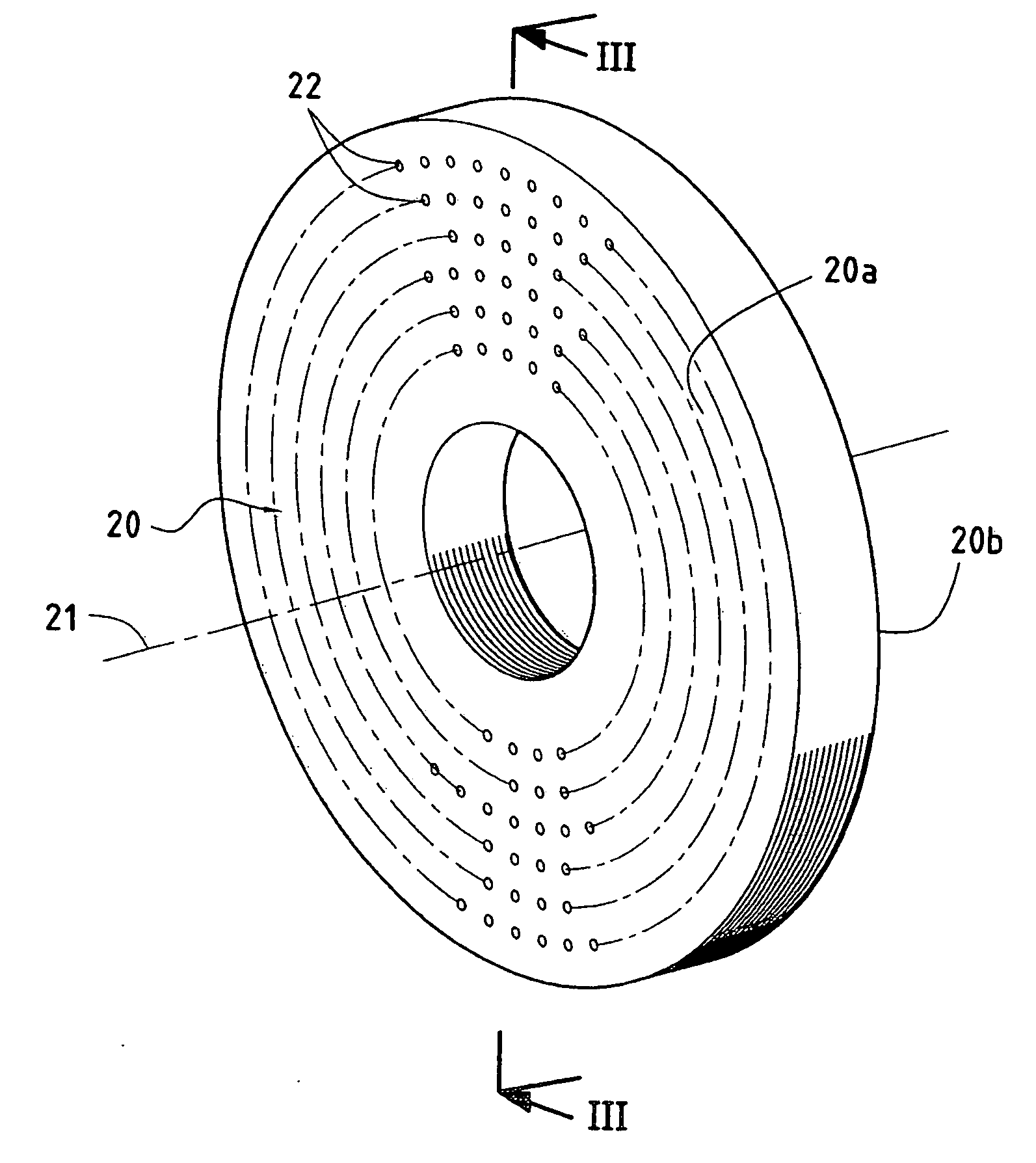
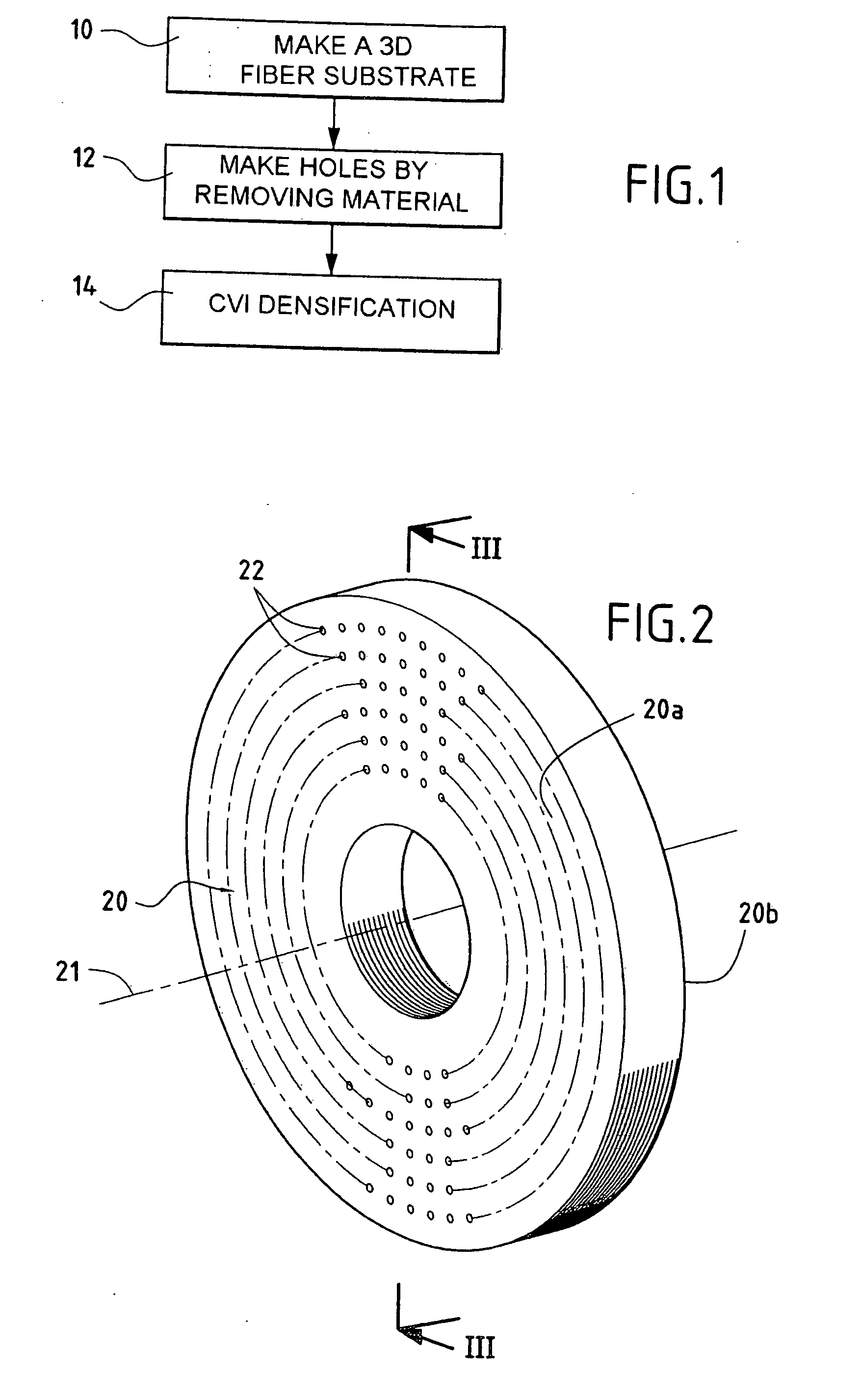
[0077]Annular fiber preforms made of carbon fibers for airplane brake disks of C / C composite material were made as follows.

[0078]Multidirectional webs were obtained by superposing three unidirectional webs of preoxidized PAN fibers, extending at angles of +60° relative to one another and bonded together by needling. The multidirectional webs were superposed and needled together progressively as they were being superposed so as to obtain a needled plate from which annular preforms of preoxidized PAN were cut out.

[0079]The preoxidized PAN preforms were subjected to heat treatment about 1600° C. to transform the PAN into carbon. This produced carbon fiber annular preforms with inner and outer diameters of 26 cm and 48 cm, a thickness of 3.5 cm, and with a fiber volume percentage of about 23%, the fiber volume percentage being the percentage of the apparent volume of the preform that is occupied by the fibers.

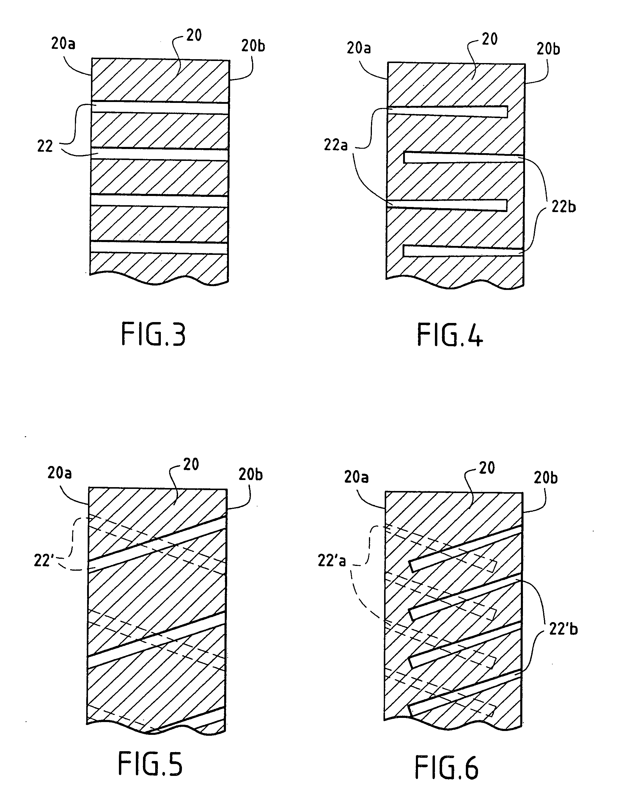
[0080]Some of the preforms were pierced with through holes parallel to the axi...

example 2

[0093]The procedure was substantially the same as in Example 1, but without intermediate scalping, preparing a load in the form of a stack of annular carbon fiber preforms for stator disks and rotor disks with different preform thicknesses lying in the range 24 mm to 36 mm, and with preforms that have been performed by a jet of water under pressure (0.5 mm diameter holes at a substantially constant density of 1 hole / cm2), and with preforms that were not perforated.

[0094]A CVI densification cycle was performed to provide a pyrolytic carbon matrix, and it was interrupted at three-quarters of its total duration in order to measure the relative density of the partially-densified preforms. Table III below gives the intermediate and final mean relative density values as measured after three-quarters of the duration of the cycle and at the end of the cycle.

TABLE IIIType ofThicknessIntermediateFinalPreformdisk(mm)densitydensityNon-perforatedStator241.651.74301.651.72361.681.70Rotor28.51.711...

example 3

[0097]The procedure was substantially the same as in Example 1, but without intermediate scalping (a single densification cycle of duration practically identical to that of the cycle in Example 2), by forming a load as a stack of annular carbon fiber preforms for brake disks, comprising non-perforated preforms and preforms perforated with different densities of holes. The holes were through holes parallel to the axis and with a diameter of 0.5 mm, and they were formed by a water jet under pressure using a square array pattern as shown in FIG. 7.

[0098]The cycle was interrupted at the end of two-thirds of its total duration in order to measure the mean intermediate density then reached. Table IV below gives the intermediate and end-of-cycle measured mean relative density values for preforms presenting differing densities of holes. The rate of density increase between the intermediate pause and the end of the cycle is also given (in density points per hour), showing deposition rate ove...


PUM

PropertyMeasurementUnit
mean diameteraaaaaaaaaa
distanceaaaaaaaaaa
diameteraaaaaaaaaa

Abstract

A composite material part is made by forming a fiber preform (20), forming holes (22) extending within the preform from at least one face thereof, and densifying the preform with a matrix formed at least in part by a chemical vapor infiltration (CVI) type process. The holes (22) are formed by removing material from the preform with fibers being ruptured, for example by machining using a jet of water under pressure, the arrangement of the fibers in the preform with the holes being substantially unchanged compared with the initial arrangement before the holes were formed. This enables the densification gradient to be greatly reduced, and it is possible in a single densification cycle to obtain a density that, in the prior art, required a plurality of cycles separated by intermediate scalping.

Description

BACKGROUND OF THE INVENTION [0001]The present invention relates to making composite material parts by forming a fiber substrate and densifying the substrate with a matrix, itself formed by a chemical vapor infiltration (CVI) type method. A particular but non-exclusive field of application for the invention is making brake disks out of carbon / carbon (C / C) composite material, in particular for airplane brakes comprising a set of disks on a common axis alternating between stator disks and rotor disks. Nevertheless, the invention is applicable to making other parts out of C / C composite material or out of other composite material, in particular out of ceramic matrix composite (CMC) material.[0002]Densifying porous substrates, such as fiber substrates or preforms, using CVI type methods, is well known.[0003]In a conventional CVI process, the substrates for densification are placed in an oven. A reaction gas is admitted into the oven for the purpose of depositing the material constituting ...

Claims


Application Information

Patent Timeline
Patent Type & Authority Applications(United States)
IPC IPC(8): B32B3/10C23C16/02B05D3/06B05D3/14D04H1/4242D04H1/43D04H1/48
CPCB23K26/381Y10T428/24273B26F1/26B32B18/00B32B2315/02C04B35/83C04B2235/614C04B2235/77C04B2235/775C04B2237/385C04B2237/62F16D69/023F16D2069/004F16D2200/0047C04B35/645C04B2235/656C04B2237/704C04B2237/76B23K26/383B23K26/385B23K26/4065B23K26/408B23K26/4085B23K26/405B23K26/382B23K26/384B23K26/40B23K26/389B23K2103/16B23K2103/38B23K2103/42B23K2103/50B23K2103/52F16D69/00
Inventor BERNARD, BRUNOGOUJARD, STEPHANEBERTRAND, SEBASTIENTHEBAULT, JACQUES
Owner SNECMA PROPULSION SOLIDE
Why Eureka
Try Eureka