Ignition Energy Control for Mixed Fuel Engine

a technology of ignition energy control and mixed fuel, which is applied in the direction of electric control, ignition automatic control, machines/engines, etc., can solve the problems of engine misfire or stall, engine exhaust, and reduced combustion quality during lower temperature conditions, so as to accelerate the degradation of the ignition system, improve combustion quality, and increase the ignition energy level

a technology of ignition energy control and mixed fuel, which is applied in the direction of electric control, ignition automatic control, machines/engines, etc., can solve the problems of engine misfire or stall, engine exhaust, and reduced combustion quality during lower temperature conditions, so as to accelerate the degradation of the ignition system, improve combustion quality, and increase the ignition energy level

US20090114188A1Inactive Publication Date: 2009-05-07FORD GLOBAL TECH LLC

Image

  • Ignition Energy Control for Mixed Fuel Engine
  • Ignition Energy Control for Mixed Fuel Engine
  • Ignition Energy Control for Mixed Fuel Engine

Examples


Embodiment Construction

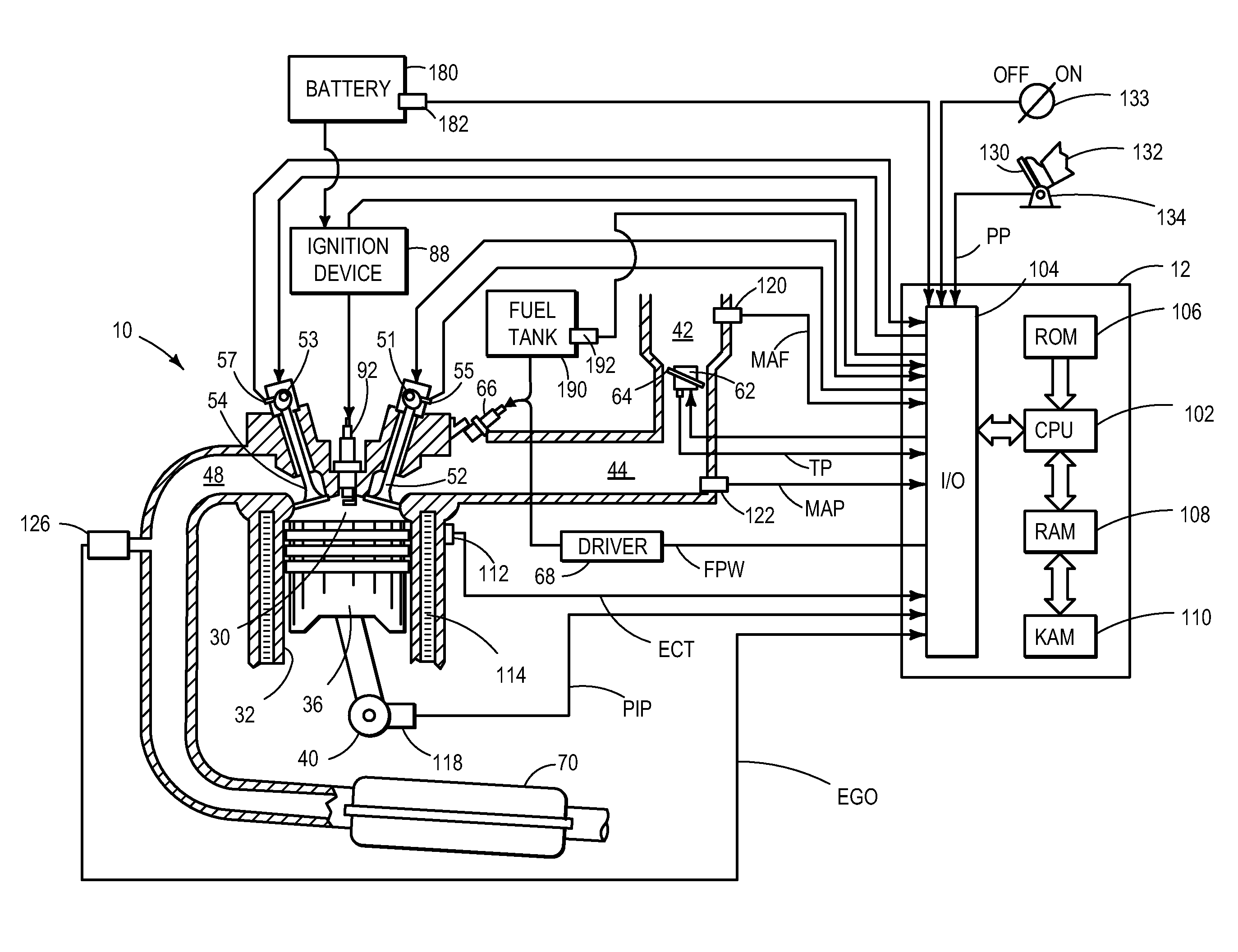
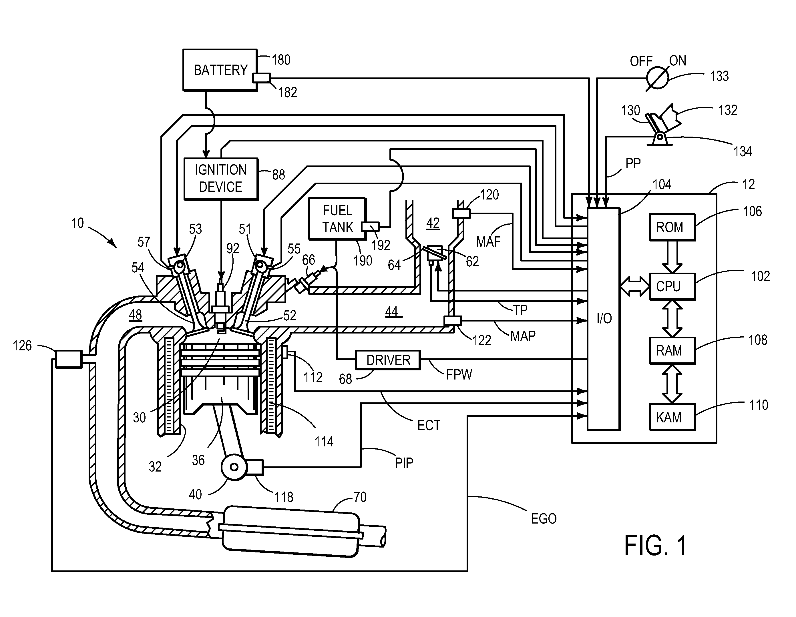
[0011]FIG. 1 shows a schematic depiction of an example combustion chamber or cylinder 30 of multi-cylinder engine system 10. As one example, engine system 10 can be configured in a vehicle propulsion system. Cylinder 30 can be defined by combustion chamber walls 32 with piston 36 moveably positioned therein. Piston 36 may be coupled to a crankshaft 40 that is operatively coupled to a drive wheel of the vehicle via a transmission. In some examples, a starter motor may be coupled to crankshaft 40 via a flywheel to enable a starting operation of engine system 10.

[0012]Cylinder 30 can receive intake air from intake manifold 44 via intake passage 42 and can exhaust combustion gases via exhaust passage 48. Intake manifold 44 and exhaust passage 48 can selectively communicate with cylinder 30 via respective intake valve 52 and exhaust valve 54. In some embodiments, cylinder 30 may include two or more intake valves and / or two or more exhaust valves.

[0013]The position of intake valve 52 may ...


PUM


Abstract

As one example, an engine system for a vehicle is provided, including an internal combustion engine having at least one cylinder; a fuel system configured to provide a fuel to the cylinder; an ignition system including at least a spark plug; a control system configured to vary a level of ignition energy provided to the cylinder via the spark plug in response to a composition of the fuel provided to the cylinder by the fuel system. A method of operating the engine system by varying a level of ignition energy provided to the engine after a start-up is also provided.

Description

SUMMARY AND BACKGROUND[0001]Some engines may be configured to utilize a fuel that includes a mixture or blend of different fuel components. As one example, some engines can utilize E85 which includes a mixture of approximately 85% ethanol and 15% gasoline. Still other engines may be configured as a flex-fuel engine, whereby a plurality of different fuel mixtures may be used by the engine. For example, a flex-fuel engine may be configured to utilize a variety of different blends of ethanol and gasoline including up to 100% gasoline, E10 which includes approximately 10% ethanol and 90% gasoline, E85, and up to 100% ethanol. Thus, engines can utilize a variety of different fuel mixtures. Alternatively, other biofuels such as methanol may be used. The inventors herein have recognized that the use of fuel mixtures that include ethanol or other biofuels such as methanol can result in reduced combustion quality during lower temperature conditions. The inventors have noted that ethanol has ...

Claims


Application Information

Patent Timeline
07 May 2009
Publication
US20090114188A1
IPC
F02P5/145
CPC
F02D35/025; F02D37/02; F02D41/0025; F02D2200/503; F02D41/064; F02P5/045; F02P9/002; F02P15/08
Inventors
PETERS, MARK WILLIAM; DEVRIES, JASON EUGENE