
Variability-Aware Asynchronous Scheme for High-Performance Communication Between an Asynchronous Circuit and a Synchronous Circuit

a high-performance communication and synchronous circuit technology, applied in the field of asynchronous logic circuits, can solve the problems of inability to store different data, and none of the previous proposals disclosed techniques adequate for a provably correct and fully automated flow

Inactive Publication Date: 2009-05-07
CO INVERSION NEOTEC +1
View PDF11 Cites 11 Cited by
  • Summary
  • Abstract
  • Description
  • Claims
  • Application Information

AI Technical Summary

Benefits of technology

"The patent describes a way to connect two circuits that work differently, called desynchronized and synchronous circuits. The method involves running both circuits at the same time, signaling a synchronization phase between them, and then exchanging information between them. The technical effect is that it allows for seamless communication between the two circuits, even if they are not perfectly synchronized."

Problems solved by technology

For these reasons, designers are conservative in their design of synchronous circuits and, in the actual circuitry, the clock often runs at a frequency slower than the one it could run at if it could dynamically adapt to any combination of process variations, data variations, and changing environmental operating conditions.
The elasticity in the data transmission requires extra storage to implement those registers that receive new incoming data but have not been able to deliver the previously stored data.
In a conventional synchronous design, it is not possible to store different data at each latch.
However, none of the previous proposals disclosed techniques adequate for a provably correct and fully automated flow covering any possible synchronous circuit.
Moreover, prior proposals included assumptions or limitations for desynchronization techniques that motivate the present disclosure.

Method used


Image

  • Variability-Aware Asynchronous Scheme for High-Performance Communication Between an Asynchronous Circuit and a Synchronous Circuit
  • Variability-Aware Asynchronous Scheme for High-Performance Communication Between an Asynchronous Circuit and a Synchronous Circuit
  • Variability-Aware Asynchronous Scheme for High-Performance Communication Between an Asynchronous Circuit and a Synchronous Circuit

Examples


embodiment 1400

[0259]Also, other partitioning of circuits are possible and envisioned. In particular, the blocks of embodiment 1400 are described in the context of resetting circuits in a series of computation pipeline stages, and such a pipeline would be reasonably fabricated in a single semiconductor die, however, computation pipelines might also be embodied across multiple semiconductor die, or embodied across multiple boards, or even embodied across multiple chassis.

Automatic Voltage and Speed Regulation

[0260]Since asynchronous circuits are tolerant to the variability of delays, they can easily incorporate self-control mechanisms that adapt the speed and power supply of the circuit to the dynamic requirements of the environment.

[0261]Certain voltage regulation approaches are based on the dynamic load presented to the computing device. A typical situation where this approach can be applied is in a data-processing circuit that processes data received from queued input data. The processing speed ...

embodiment 1950

[0272]The voltage regulators 1921, 1923 and 1925 can be instanced to each controller independently. In the embodiment shown each regulator 1921, 1923 and 1925 is connected to a common power rail Vdd, and produces a regulated Vdd voltage on a voltage supply rail 1941, 1942, 1943 that in turn powers supply voltage connections to the circuit elements in the data path (which supply connections are not shown in the embodiment 1950).

[0273]The aforementioned descriptions apply to the two-phase controllers described herein. Notwithstanding, one or more of the techniques for regulating voltage to maximize power efficiency in a circuit might be applied in a system implementing a four-phase protocol. Moreover, while the aforementioned techniques disclose voltage regulation of the supply voltage, techniques to change voltage biasing might as well be applied within the context of the embodiments of the invention herein.

[0274]The electronic systems into which various embodiments of the present in...


PUM


Abstract

A system for automatically transforming a given synchronous circuit description into an equivalent and provably correct desynchronized circuit description. Included in the automated transformation are techniques for synthesizing a variability-aware controller using a two-phase protocol, techniques for synthesizing a variability-aware controller using gated clocks and testability circuits, techniques for synthesizing a variability-aware controller optimized for performance, techniques for initializing the synthesized controller, techniques for dynamically minimizing power requirements, and techniques for interfacing the desynchronized circuit with external synchronous circuits. Also disclosed are techniques for implementing a system for automatically transforming a synchronous circuit description into an equivalent and provably correct desynchronized circuit description within the context of an electronic design automation design flow. Exemplary circuits used in the application of the aforementioned techniques are provided. Application of mathematical models and techniques used for proving equivalence between the input description and the resulting desynchronized circuit are presented and explained.

Description

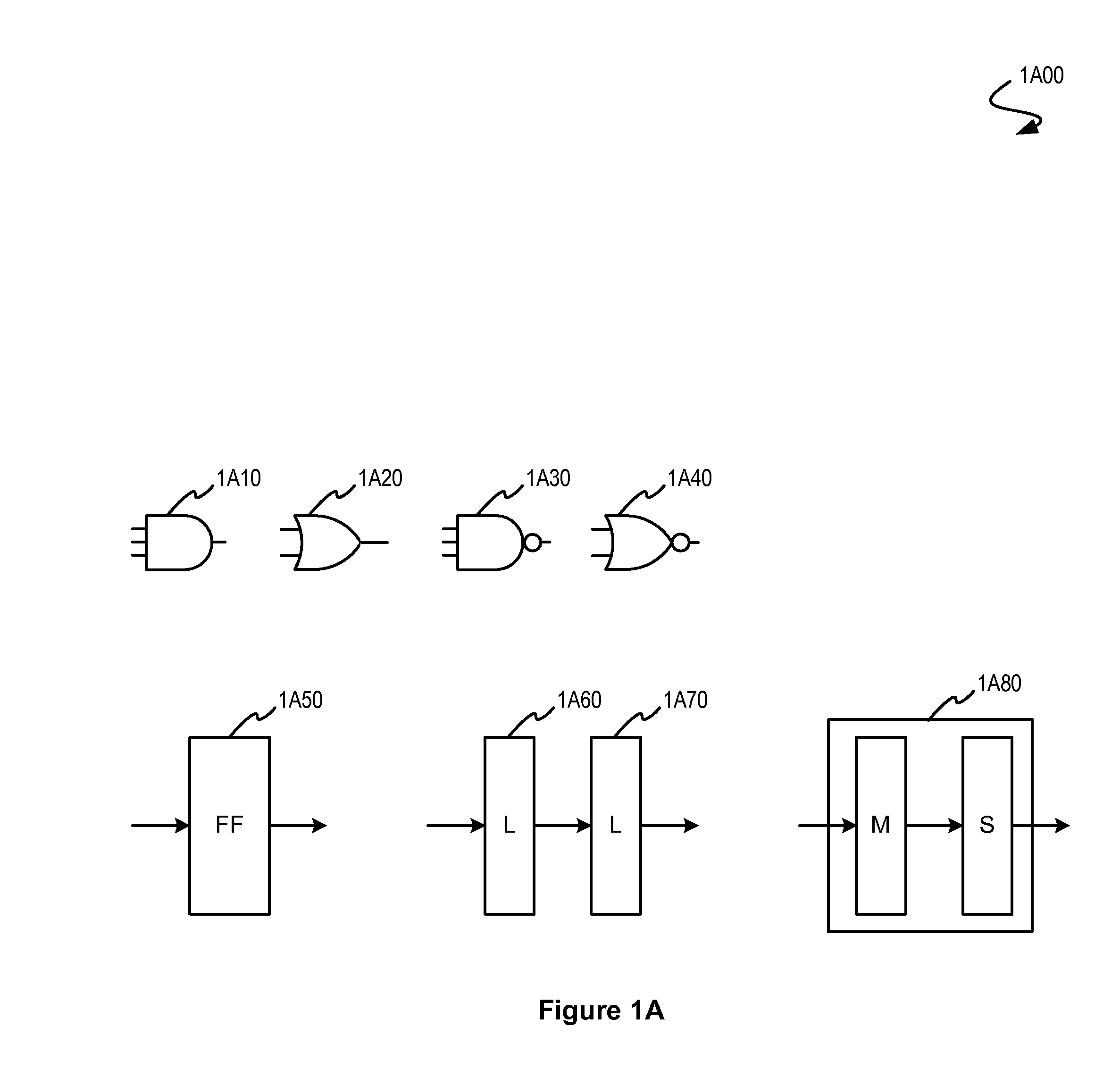
CLAIM OF PRIORITY[0001]The present Application for Patent claims priority to Provisional Application No. 60 / 985,878 entitled “A Variability-Aware Asynchronous Scheme Based on Two-Phase Protocols and Delay Matching” filed Nov. 6, 2007, and assigned to the assignee hereof and hereby expressly incorporated by reference herein.FIELD OF THE INVENTION[0002]The present invention relates to asynchronous logic circuits and more particularly to automated synthesis thereof.BACKGROUND OF THE INVENTION[0003]A digital circuit is composed of two types of components: combinational and sequential. As shown in FIG. 1A the combinational components 1A10, 1A20, 1A30, and 1A40 implement Boolean functions, whereas the sequential components 1A50, 1A60, 1A70, and 1A80 act as memory elements that store the state of the circuit. The sequential components are usually implemented with flip-flops 1A50, or latches 1A60, and 1A70, or sometimes combinations of latches 1A80 in a master / slave arrangement. Most digita...

Claims


Application Information

Patent Timeline
Patent Type & Authority Applications(United States)
IPC IPC(8): H04B1/00H04L7/00
CPCH03K19/20G06F2217/14G06F17/505H03L7/00G06F30/327G06F30/333
Inventor CORTADELLA, JORDISINGHAL, VIGYANTUNCER, EMRELAVAGNO, LUCIANO
Owner CO INVERSION NEOTEC
Learn More