Gas supply device, substrate processing apparatus and substrate processing method

a technology of gas supply device and substrate, which is applied in the direction of transportation and packaging, chemical vapor deposition coating, coating, etc., can solve the problems of insufficient security of in-plane uniformity, difficult to correct the characteristics of an outermost circumference of a peripheral edge of the substrate, and inability to achieve uniform processing characteristics. , to achieve the effect of efficient correction and optimization of processing characteristics

Active Publication Date: 2009-05-07
TOKYO ELECTRON LTD
View PDF16 Cites 312 Cited by
  • Summary
  • Abstract
  • Description
  • Claims
  • Application Information

AI Technical Summary

Benefits of technology

[0042]In the present invention, the gas introduction member provided in the processing chamber includes a plurality of inner gas inlet portions and an outer gas inlet portion. The processing gas is supplied from the plurality of inner gas inlet portions to the target substrate arrangement region in a controlled split flow rate ratio. The additional gas for adjusting the processing characteristics of the processing gas is allowed to flow from the outer gas inlet portion to the region outside the outermost periphery of the target substrate. These features make it possible to efficiently correct and optimize the processing characteristics in the outermost circumferential region of the target substrate, thus making the processing characteristics more uniform. In other words, it is difficult to correct the processing characteristics of the outermost circumferential region of the target substrate even though the additional gas is supplied to the edge region of the target substrate. However, if the additional gas is supplied to the region outside the outermost periphery of the target substrate, the additional gas acts effectively on the outermost circumferential region of the target substrate. This makes it possible to correct the processing characteristics of the outermost circumferential region.
[0043]Furthermore, the present gas supply device is provided with the processing gas inlet portion for introducing the processing gas into the processing chamber and the additional gas inlet portion for introducing the additional gas into the processing chamber, so that the processing gas and the additional gas can be supplied to the target substrate. The gas supply device is further provided with the switching mechanism for switching, when the additional gas is not introduced into the processing chamber, the path in such a manner as to allow the processing gas to flow through the additional gas inlet portion. These features allow the processing gas to flow through the additional gas inlet portion in case of not introducing the additional gas. This makes it possible to eliminate the possibility that no gas flows through the gas injection holes of the additional gas inlet portion during the course of processing. As a consequence, it is possible to avoid generation of a deposit in the gas injection holes of the additional gas inlet portion. In case of plasma processing, it is possible to prevent an abnormal electric discharge from being generated in the gas injection holes.

Problems solved by technology

However, requirements for in-plane uniformity of the substrate become more and more strict.
In particular, it is difficult to correct the characteristics of an outermost circumference of a peripheral edge of the substrate.
Therefore, it sometimes happens that the in-plane uniformity is not sufficiently secured by merely employing the techniques mentioned above.
In case where an additional gas line is separately provided as in JP2007-214295A, there is a possibility that, if the additional gas is not supplied, a deposit may be accumulated in injection holes through which the additional gas is to be injected and an abnormal electric discharge may be generated in the vicinities of the injection holes.

Method used


Image

  • Gas supply device, substrate processing apparatus and substrate processing method
  • Gas supply device, substrate processing apparatus and substrate processing method
  • Gas supply device, substrate processing apparatus and substrate processing method

Examples


Embodiment Construction

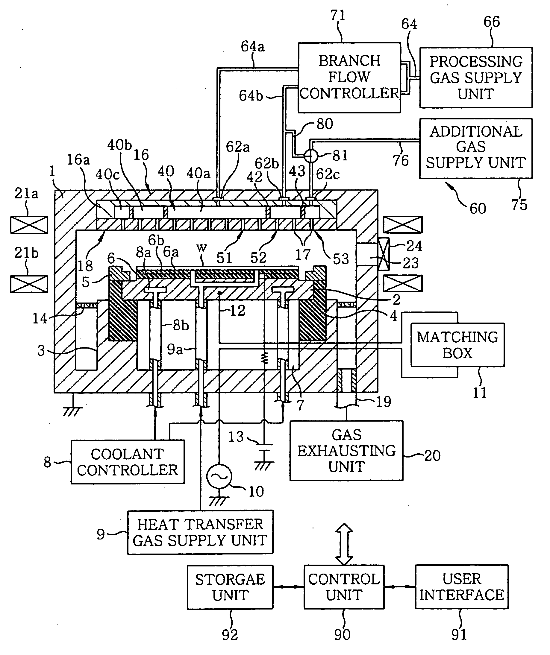
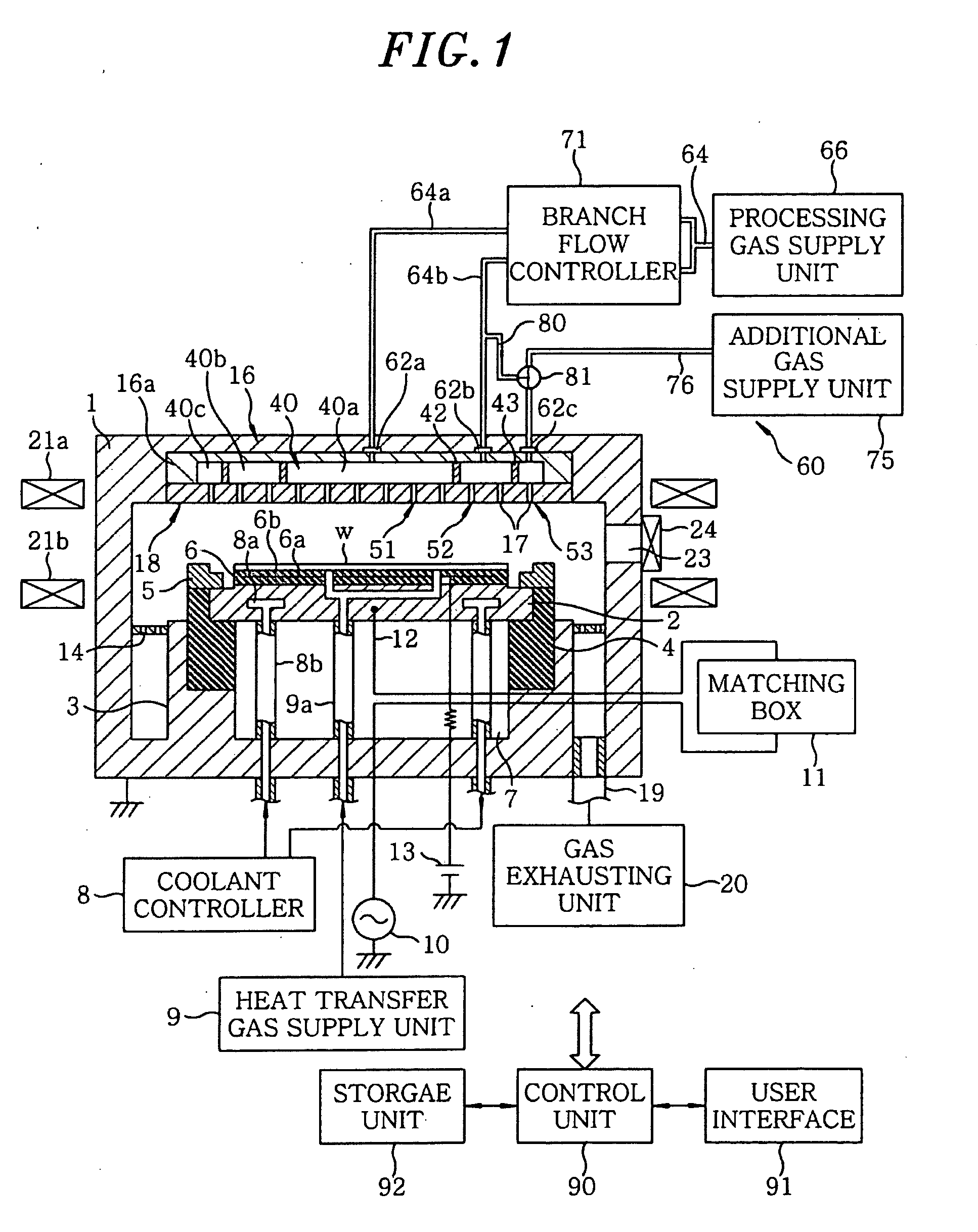
[0057]Hereinafter, an embodiment of the present invention will be described with reference to the accompanying drawings which form a part hereof. FIG. 1 is a schematic cross sectional view showing a plasma etching apparatus as a substrate processing apparatus to which a gas supply device is applied in accordance with an embodiment of the present invention. FIG. 2 is a bottom plan view showing a shower head employed in the plasma etching apparatus shown in FIG. 1.

[0058]The plasma etching apparatus is a capacitively coupled parallel plate type plasma etching apparatus. The plasma etching apparatus includes a substantially cylindrical airtight chamber 1 of which wall is formed of, e.g., an aluminum material having an oxidized surface. The chamber 1 is electrically grounded.

[0059]In the chamber 1, there is provided a support table 2 for horizontally supporting a semiconductor wafer (hereinafter simply referred to as a “wafer”) W as a target substrate to be processed, the support table 2...


PUM

PropertyMeasurementUnit
frequencyaaaaaaaaaa
pressureaaaaaaaaaa
frequencyaaaaaaaaaa

Abstract

A gas supply mechanism includes a gas introduction member having gas inlet portions through which a gas is introduced into a processing chamber, a processing gas supply unit, a processing gas supply path, branch paths, an additional gas supply unit and an additional gas supply path. The gas inlet portions includes inner gas inlet portions for supplying the gas toward a region where a target substrate is positioned in the chamber and an outer gas inlet portion for introducing the gas toward a region outside an outermost periphery of the target substrate. The branch paths are connected to the inner gas inlet portions, and the additional gas supply path is connected to the outer gas inlet portion.

Description

FIELD OF THE INVENTION[0001]The present invention relates to a gas supply device for supplying a gas into a processing chamber when a substrate is subjected to a substrate processing such as plasma etching or the like, a substrate processing apparatus including the gas supply device and a substrate processing method.BACKGROUND OF THE INVENTION[0002]In a manufacturing process of electronic devices such as semiconductor devices and liquid crystal displays, a substrate processing, e.g., film-forming processing for forming a predetermined film on the surface of a substrate or an etching processing for forming specific patterns to a film formed on a substrate is performed.[0003]In the substrate processing, a plasma is used to obtain high reactivity. In particular, a plasma etching apparatus is frequently used in the etching processing. The plasma etching apparatus includes a processing chamber having a substrate therein, a lower electrode provided in the processing chamber for mounting t...

Claims


Application Information

Patent Timeline
Patent Type & Authority Applications(United States)
IPC IPC(8): H01L21/3065
CPCC23C16/45561C23C16/45565H01L21/3065H01L21/67069C23C16/45574Y10T137/877H01L21/02H01L21/205
Inventor MASUDA, NORIIKI
Owner TOKYO ELECTRON LTD
Why Eureka
Try Eureka