Step-up/down switching regulator

Inactive Publication Date: 2009-05-14
ROHM CO LTD
View PDF7 Cites 12 Cited by
  • Summary
  • Abstract
  • Description
  • Claims
  • Application Information

AI Technical Summary

Benefits of technology

[0031]According to the embodiment, a current that flows via a back gate of the synchronous rectifier transistor or the switching transistor is controlled; and accordingly, an inrush current

Problems solved by technology

In the latter case, efficiency when a current supplied to a load is small is inferior to the former case; however, since the transistor is used in place of the diode, integration can be made in the inside of a large scale integrated circuit (referred to as LSI); and consequently, reduction in size is possible as a circuit area including peripheral components.
In the case where a P-channel metal oxide semiconductor field effect transistor (referred to as P-channel MOSFET) is used in the synchronous rectifier transistor and a back gate thereof is connected to a source (or drain), there is a problem i

Method used


Image

  • Step-up/down switching regulator
  • Step-up/down switching regulator
  • Step-up/down switching regulator

Examples


Example

First Embodiment

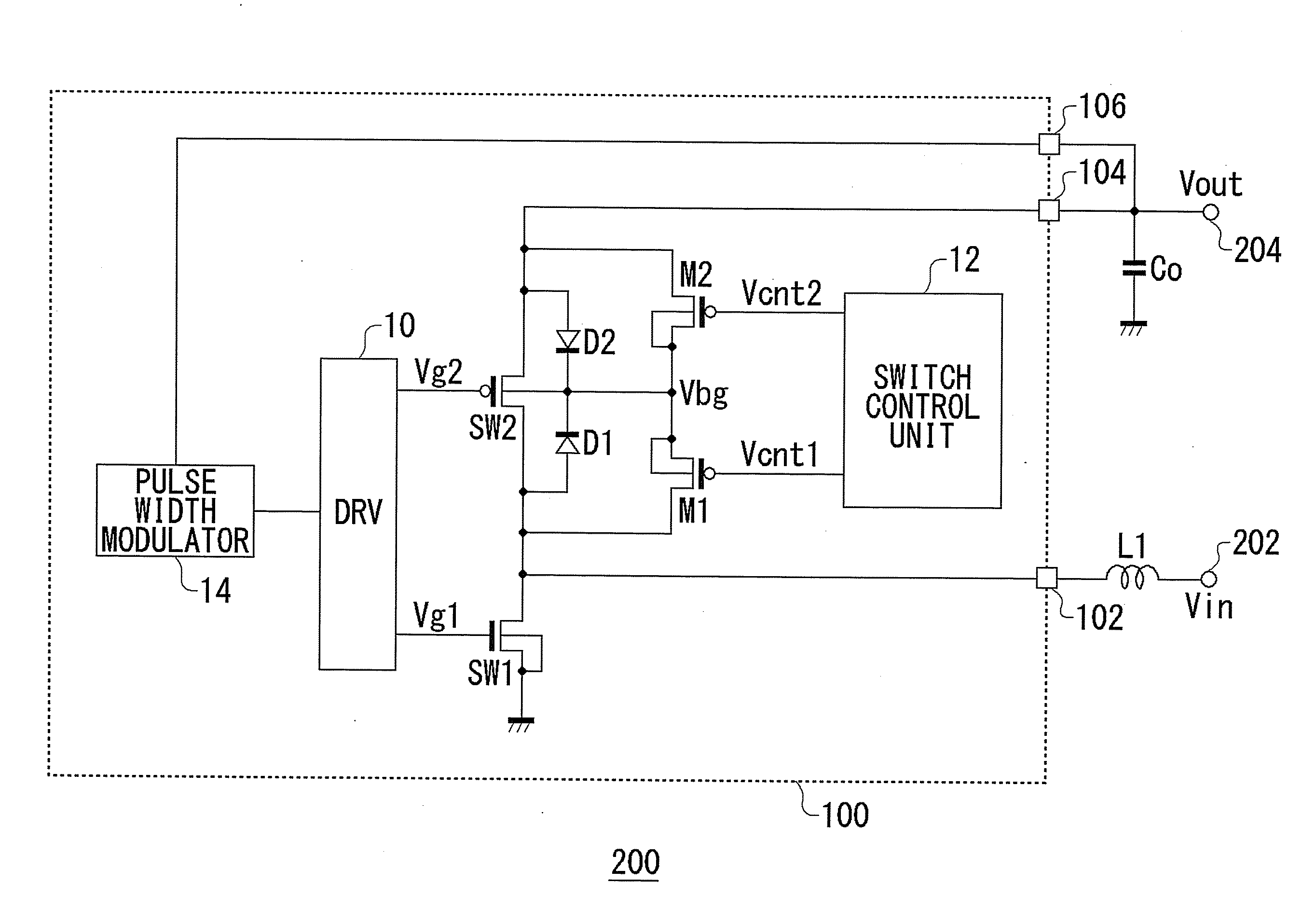
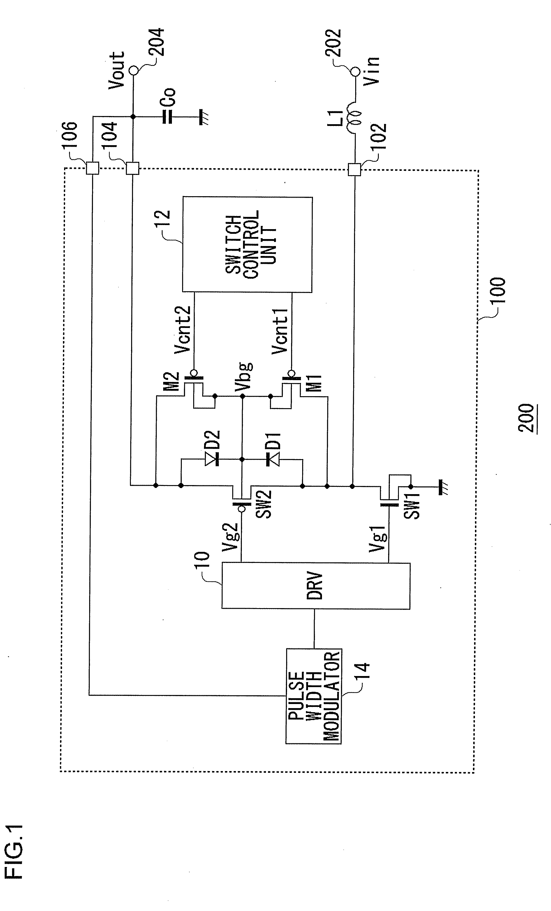
[0042]A first embodiment according to the present invention relates to a step-up switching regulator of a synchronous rectifying system. FIG. 1 is a circuit diagram showing a configuration of a step-up switching regulator 200 according to the first embodiment. The step-up switching regulator 200 is a switching regulator of the synchronous rectifying system including a control circuit 100, an inductor L1, and an output capacitor Co.

[0043]An input voltage Vin is applied to an input terminal 202. The step-up switching regulator 200 according to the present embodiment steps up the input voltage Vin at a predetermined step-up rate, and outputs an output voltage Vout from an output terminal 204.

[0044]The inductor L1 is connected between a first terminal 102 of the control circuit 100 and the input terminal 202 of the step-up switching regulator 200. The input voltage Vin is supplied to the first terminal 102 via the inductor L1. The output capacitor Co is connected between...

Example

Second Embodiment

[0059]A second embodiment relates to a step-down switching regulator 210 of a synchronous rectifying system. FIG. 3 is a circuit diagram showing a configuration of the step-down switching regulator 210 according to the second embodiment. The step-down switching regulator 210 is a switching regulator of the synchronous rectifying system including a control circuit 110, an inductor L1, and an output capacitor Co. In the same drawing, the same reference numerals are given to those identical or equivalent to constitutional elements in FIG. 1; and their description will be arbitrarily omitted.

[0060]An input voltage Vin is applied to an input terminal 212. The step-down switching regulator 210 according to the present embodiment steps down the input voltage Vin, and outputs an output voltage Vout from an output terminal 214. The inductor L1 is connected between a first terminal 112 of the control circuit 110 and the output terminal 214 of the step-down switching regulator...

Example

Third Embodiment

[0074]The control circuit 100 shown in FIG. 1 and the control circuit 110 shown in FIG. 3 are equivalent in circuit configuration; and arrangement of the externally provided inductor L1 and output capacitor Co and appearing positions of the input voltage Vin and the output voltage Vout are different. Consequently, in a third embodiment, the control circuit 100 shown in FIG. 1 and the control circuit 110 shown in FIG. 3 are used as a control circuit for a switchable step-up / down switching regulator.

[0075]FIG. 5 is a circuit diagram showing a configuration of a control circuit 120 according to the third embodiment. The control circuit 120 includes a first switching transistor SW5, a second switching transistor SW6, a first transistor M1, a second transistor M2, a driver circuit 10, a switch control unit 12, and a pulse width modulator 14. The first switching transistor SW5 serves as a switching transistor at a step-up mode; and serves as a synchronous rectifier transis...


PUM


Abstract

An input voltage Vin is supplied to a first terminal of a control circuit via an inductor connected to outside, and an output capacitor is connected to a second terminal. A switching transistor is provided between the first terminal and ground, and a synchronous rectifier transistor is provided between the first terminal and the second terminal. A first transistor is provided between a back gate of a synchronous rectifier transistor and the first terminal, and a second transistor is provided between the back gate and the second terminal. A switch control unit turns OFF the first transistor and the second transistor at a step-up stop interval; and turns OFF the first transistor and turns ON the second transistor at a step-up operation interval.

Description

BACKGROUND OF THE INVENTION[0001]1. Field of the Invention[0002]The present invention relates to switching regulators and, more particularly, relates to a step-up or step-down switching regulator of a synchronous rectifying system.[0003]2. Description of the Related Art[0004]Recent various electronic apparatuses such as a mobile phone, a personal digital assistant (referred to as PDA), and a notebook-sized personal computer are mounted with many devices, for example, a light emitting diode (referred to as LED hereinafter) provided as a liquid crystal backlight, a microprocessor, or other analog and digital circuits, which operate at different power supply voltages.[0005]On the other hand, a battery such as a lithium ion battery is mounted on such electronic apparatuses as a power supply. In order to supply a voltage output from the lithium ion battery to devices which operate at different power supply voltages, there is used a direct current (referred to as DC) / DC converter such as ...

Claims


Application Information

Patent Timeline
IPC IPC(8): H02M7/217
CPCY02B70/1466H02M3/1588Y02B70/10
Inventor KARASAWA, SHINYA
Owner ROHM CO LTD
Why Eureka
Try Eureka