Solid Particle Erosion Resistant Surface Treated Coat and Rotating Machine Applied Therewith

a surface treatment and erosion resistance technology, applied in the direction of machines/engines, solid-state diffusion coatings, natural mineral layered products, etc., can solve the problems of surface treatment being barely applied to rotating members, fatigue strength deterioration, and shortening the life of rotating members, etc., to achieve high erosion resistance

Active Publication Date: 2009-05-14
MITSUBISHI HEAVY INDUSTIES COMPRESSOR CORP
View PDF3 Cites 41 Cited by
  • Summary
  • Abstract
  • Description
  • Claims
  • Application Information

AI Technical Summary

Benefits of technology

(2) According to the invention of claim 2, in addition to the function and effect of the invention of claim 1, the nitrided hard layer is formed by the radical nitriding method. Thus, the nitrided hard layer so formed has no brittle degenerated layer and becomes strong against the fatigue characteristic. Hence, the fatigue strength can be enhanced as compared with the fatigue characteristic of the base material.
[0012]According to the invention of claim 12, by the function and effect of the invention of any one of claims 1 to 11, a steam turbine that has a high erosion resistance, oxidation resistance and fatigue strength and enables to elongate the life can be obtained.

Problems solved by technology

However, in case of the above-mentioned 12% chromium stainless steel, there is a problem in that the parts and components are damaged by erosions due to solid particles included in the steam, such as silica, iron oxide or the like, so that their life becomes shorter.
Nevertheless, even in this case, a sufficient resistance against erosions due to solid particles is hardly obtained so that the fatigue strength is deteriorated.
Thus, there is a problem that the above-mentioned surface treatment is hardly applied to rotating members.
Nevertheless, if an application to the part making contact with steam in a steam turbine is considered, practicability and applicability of such a surface treated coat are still insufficient not only with respect to the solid particle erosion resistance but also with respect to the oxidation resistance, fatigue strength or the like.

Method used


Image

  • Solid Particle Erosion Resistant Surface Treated Coat and Rotating Machine Applied Therewith
  • Solid Particle Erosion Resistant Surface Treated Coat and Rotating Machine Applied Therewith
  • Solid Particle Erosion Resistant Surface Treated Coat and Rotating Machine Applied Therewith

Examples


embodiment 1

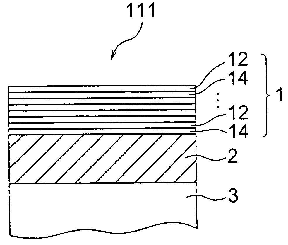
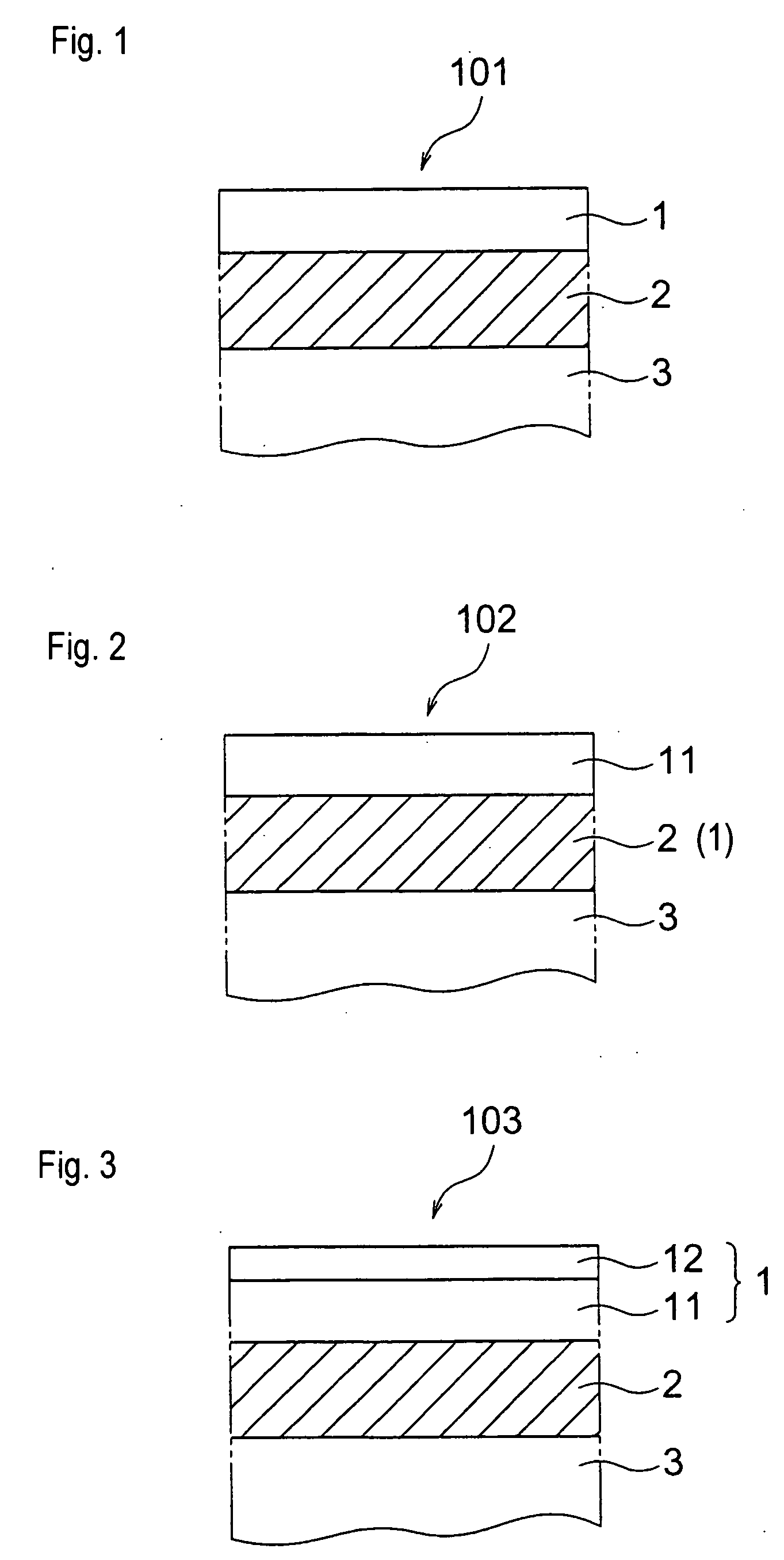
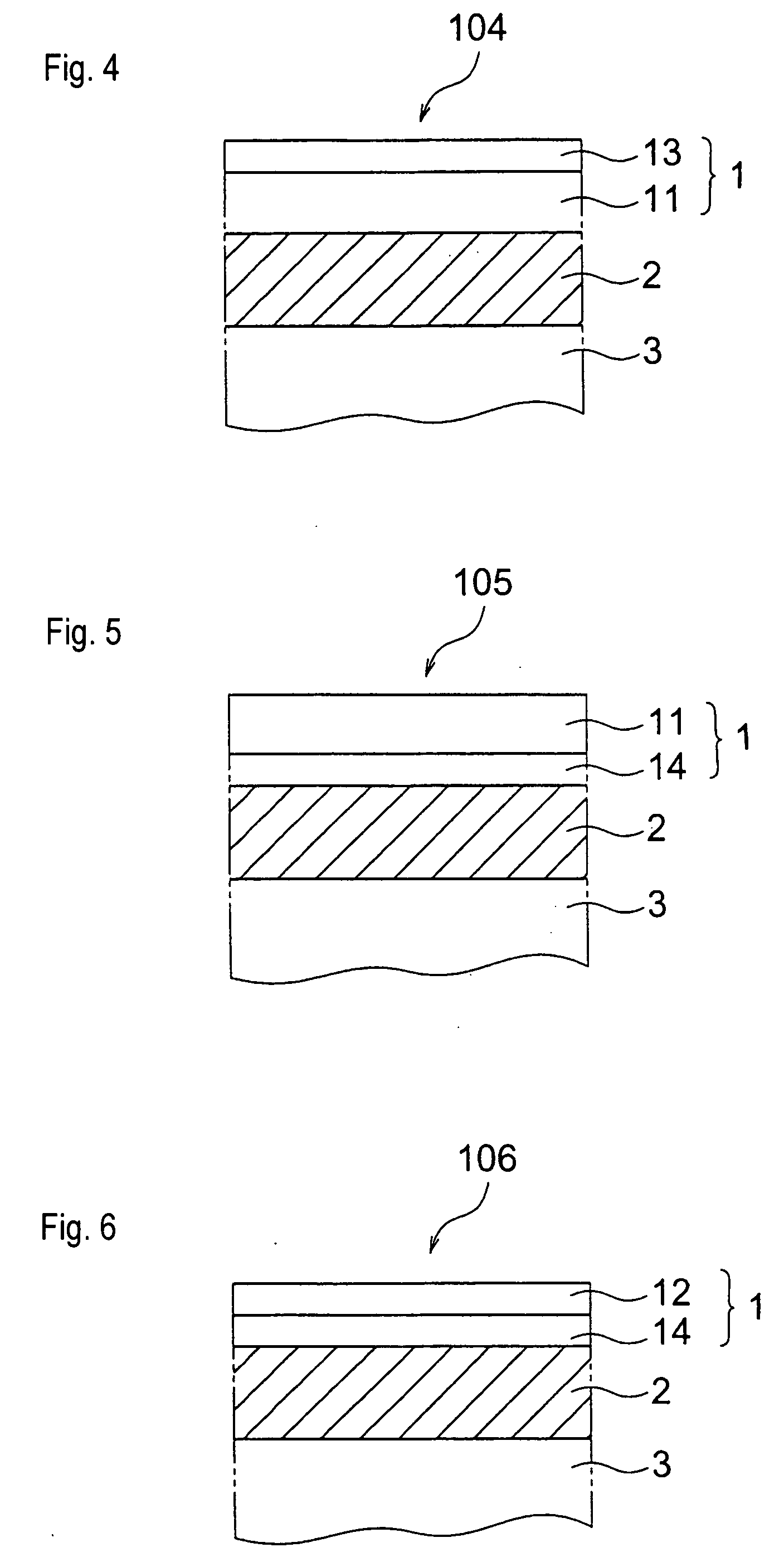
[0026]FIG. 1 is an explanatory cross sectional view of a solid particle erosion resistant surface treated coat 101 of the embodiment 1 according to the present invention. The solid particle erosion resistant surface treated coat 101 of the present embodiment is constructed by a nitrided hard layer 2 formed on a base material 3 and a PVD (physical vapor deposition) hard layer 1 formed on the nitrided hard layer 2 as a hard layer formed by the PVD method. Also, a steam turbine as a rotating machine according to the present invention is applied with the solid particle erosion resistant surface treated coat so constructed.

[0027]The nitrided hard layer 2 is preferably a radical nitrided layer formed by a radical nitriding method and its thickness is set to 30 μm or more, preferably to 60 to 100 μm, in order to suppress a deterioration of the fatigue strength and enhance the solid particle erosion resistance. The PVD hard layer 1 formed thereon has a total thickness of 10 μm or more, pref...

embodiment 2

[0029]FIG. 2 is an explanatory cross sectional view of a solid particle erosion resistant surface treated coat 102 of the embodiment 2 according to the present invention. The solid particle erosion resistant surface treated coat 102 of the present embodiment is constructed by the nitrided hard layer 2, that is the same as described with respect to the embodiment 1, formed on the base material 3 and the PVD hard layer 1 that is a CrN layer 11 formed on the nitrided hard layer 2 by the PVD.

[0030]The nitrided hard layer 2 is a layer, having no degenerated layer, formed by the radical nitriding method and its thickness is set to 30 μm or more, preferably to 60 to 100 μm. If this thickness is less than 30 μm, in the environment where the solid particles collide, the upper PVD hard layer 1 together with the base material 3 is deformed at the time of collisions by the solid particles so that the upper PVD hard layer 1 may crack or peel off and this causes a problem to deteriorate the erosi...

embodiment 3

[0032]FIG. 3 is an explanatory cross sectional view of a solid particle erosion resistant surface treated coat 103 of the embodiment 3 according to the present invention. The solid particle erosion resistant surface treated coat 103 of the present embodiment is constructed by the nitrided hard layer 2, that is the same as described with respect to the embodiment 1, formed on the base material 3 and the PVD hard layer 1 comprising the CrN layer 11 likewise formed on the nitrided hard layer 2 by the PVD and a TiAlN layer 12 formed on the CrN layer 11 by the PVD. Like the CrN layer 11, the TiAlN layer 12 can be formed, for example, by the arc type ion plating method and its thickness is set to 1 to 6 μm.


PUM

PropertyMeasurementUnit
thicknessaaaaaaaaaa
thicknessaaaaaaaaaa
thicknessaaaaaaaaaa

Abstract

A solid particle erosion resistant surface treated coat is provided by which a solid, particle erosion resistance is largely enhanced and a rotating member is given with an oxidation resistance without deteriorating a fatigue strength. Also, a rotating machine, such as a steam turbine, axial compressor or the like, applied with this coat is provided. The solid particle erosion resistant surface treated coat comprises a nitrided hard layer formed on a surface of base material and a PVD (physical vapor deposition) hard layer of at least one layer formed on the nitrided hard layer by a PVD method. The nitrided hard layer has a thickness of at least 30 μm. The PVD hard layer has a total thickness of at least 10 μm. Deformation of the base material by collisions by solid particles is prevented and crack of the coat comprising the nitrided hard layer formed on the base material and the PVD hard layer formed on the nitrided hard layer is prevented. Thereby, the solid particle erosion resistance is secured, life of the solid particle erosion resistant surface treated coat can be elongated and the oxidation resistance and fatigue strength are enhanced.

Description

TECHNICAL FIELD[0001]The present invention relates to a surface treated coat having a solid particle erosion resistance and also relates to a rotating machine applied with this surface treated coat, such as a steam turbine, axial compressor or the like (such rotating machine is simply referred to as a rotating machine in the present specification and claims for patent as appended herein).BACKGROUND OF THE INVENTION[0002]In a steam turbine, as a base material of parts and components making direct contact with steam, a 12% chromium stainless steel, for example, is used. In order to improve a resistance against erosions caused by solid particles existing in the steam, in case of stationary parts and components, a surface of the base material is often applied with a boronizing treatment in which a penetration diffusion treatment of boron is carried out.[0003]However, in case of the above-mentioned 12% chromium stainless steel, there is a problem in that the parts and components are dama...

Claims


Application Information

Patent Timeline
Patent Type & Authority Applications(United States)
IPC IPC(8): B32B18/00
CPCC23C8/80Y10T428/12736C23C28/04F01D5/288F04D29/023F05D2220/31F05D2230/31C23C28/42F05D2300/228Y10T428/2991Y10T428/2993Y10T428/265Y10T428/12028Y10T428/12181Y10T428/12847C23C14/0641F05D2300/611
Inventor YASUI, TOYOAKIYAMADA, YOSHIKAZUIWASAKI, SHUGOHANANAKA, KATSUYASUIKENO, KYOICHI
Owner MITSUBISHI HEAVY INDUSTIES COMPRESSOR CORP
Why Eureka
Try Eureka